background image

Page 26

CREASING

DIAGNOSTICS and CALIBRATION TOOLS.

SET THE MEASUREMENT SYSTEM (METRIC / IMPERIAL SETTINGS).

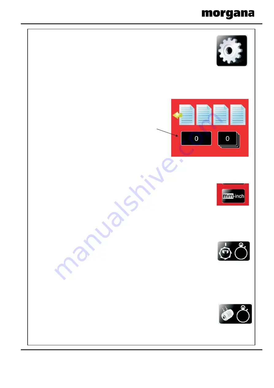
To set the total counter to zero.
Turn the Machine on.
Insert the Engineers Plug into the Socket located at the rear of the machine.
Select Tools on the Display and select this button,
this value denotes the Machine total count.

To set the measurement system for Imperial (Inch) or Metric (mm) the following procedure
Is necessary.
Turn the machine on.
Insert the Engineers Plug into the Socket located at the rear of the machine.
Select Tools on the Display and select
‘METRIC or IMPERIAL’ by toggling the button.
Return to the main screen and remove the engineers plug.

To enter the engineers tools menu.
Turn the Machine on.
Insert the Engineers Plug into the Socket located at the rear of the machine.
Select Tools on the Display and continue to select required tool.

To set the vacuum drum start position the following procedure Is necessary.
Turn the machine on.
Insert the Engineers Plug into the Socket located at the rear of the machine.
Select Tools on the Display and select ‘Vac Drum Trim’ by toggling the button.
Input a value and run, repeat until start position is correct under the papergate.
Return to the main screen and remove the engineers plug.

To set the vacuum drum suction start time the following procedure Is necessary.
Turn the machine on.
Insert the Engineers Plug into the Socket located at the rear of the machine.
Select Tools on the Display and select ‘Vac Suck Trim’ by toggling the button.
Input a value and run, repeat until start delay is correct.
Return to the main screen and remove the engineers plug.

SET THE TOTAL COUNT TO ZERO.

SETTING THE VACUUM DRUM POSITION.

SETTING THE VACUUM DRUM SUCTION DELAY.

Counter button

Summary of Contents for AutoCreaser Pro 33

Page 1: ...sue 5 APRIL 2013 AutoCreaser Pro 33 CB UL SERVICE MANUAL Document Creasing Machine Morgana Systems Limited United Kingdom www morgana co uk Telephone 01908 608888 Facsimile 01908 692399 Serial No 740866 Onwards ...

Page 2: ...nes illustrated parts manual available when servicing as its illustrations provide an invaluable reference to the construction of the individual assemblies used to build the machine All threaded fasteners are isometric all nuts are isometric hexagon All screws are hardened high tensile steel Cap head Button head Socket countersunk Shoulder bolts and Grubscrews have internal hexagon drives which re...

Page 3: ...PS DRIVERS THESE WILL DAMAGE THE SCREWS MAY SLIP CAUSING DAMAGE OR INJURY iii iv Identification New Machine Preparation For general identification of areas of the machines the following terms are used Operator side control consul facing Rear of machine opposite to control consul Delivery end to the left of the operator side Feeder end on your right Remove all packaging materials All metal parts in...

Page 4: ... absorber Drive Link Refurbishment Electrics The PRO Control System Optical Sensors Cleaning and Setting Trouble Shooting i Introduction Fasteners Identification iv New Machine Preparation Suction Drum and Belt Removal Replacement Removal of Unit Removal of Unit Removal Refitting PCBs Diagnostics Setting the Measurement System Metric Inch Setting the Language English French German Autocreaser Pro ...

Page 5: ... 9 10 11 12 4 1 2 3 5 6 7 8 1 Roller tilt handle 6 Air seperation knob 11 Paper Gate 2 Stacker assembly 7 Adjustable side lay 12 Exit Guard 3 Suction slot knob 8 Back stop 13 Switch Panel 4 Touchscreen 9 Fixed side lay 14 Fuses 5 Air distribution knob 10 Roller tilt knob AutoCreaser Pro 33 ...

Page 6: ...s at the opposite side and is secured by four screws This cover is removed by lifting up and outward to unhook the keyhole locations on the opposite side to the screw fittings This allows access to the electronic plate assembly The creaser mechanism is situated towards the delivery end of the machine and is covered by a fixed and a hinged guard To remove these guards just remove the four screws M4...

Page 7: ... and using a 3mmA F allen key unscrew until clear of the plate 8 Twist the vacuum drum towards the motor to clear the bearing plate location hole and withdraw the drum assembly clear of the machine Replacing the Vacuum Drum assembly Replacement is the reverse procedure 1 Place the delrin block loosely in position 2 Ensuring the end plug is correctly located in the end of choke tube the vacuum drum...

Page 8: ...r 1 Remove the Compressor cover below the feed bed and the rear cover 2 Remove the top stainless steel feed bed 3 Remove the moving side guide 4 Unplug the motor or the sensor from the respective PCB at the rear of the machine and feed the wire up through the access holes 5 Unscrew the motor or the sensor from the motor mounting bracket and remove Replacement is the reverse procedure To tension th...

Page 9: ...SYSTEM AutoCreaser Pro 33 Page 9 BLANK PAGE ...

Page 10: ...rds the back of the machine 3 1 Remove the two pipe mounting clip plates ITEM 5 on page 11 so that the hoses can be detached from the valve 3 2 Remove the two screws that secure the valve to the underside of the feed bed When refitting the valve ensure that the ends of the hoses are clear of nylon fibres and that the O ring is in place NOTE ...

Page 11: ...ER QTY Description 1 1 2 175 164 01 Valve Block Tube Stepper 3 173 65 01 1 Valve Motor Lead Assembly 175 176 01 1 4 2 Pipe Mounting Clip 5 175 166 01 Solid Butterfly 1 6 401 02 040 008 Dowel Pin Ø3 x 12 Lg 7 601 168 2 8 1 602 178 175 177 01 Upper Valve Spacer 9 1 1 10 11 12 603 108 6 Screw Pan Pozi Taptite M4 x 8 Lg 404 01 030 008 4 Screw Socket Countersunk Hd M3 x 8 Lg 13 173 67 01 409 01 030 008...

Page 12: ...Page 12 CREASING BLANK PAGE ...

Page 13: ...le mounting retaining wiring loom Ensure that the mains is unplugged 4 4 From the rear of the machine remove two button socket screws with their washers 4 5 Remove the unlock knob from the front of the machine 4 6 Remove the polycord drive belt from the suction drum 4 7 The unit can be lifted by two people vertically out of the main frame with care One person should be guiding the wiring and plugs...

Page 14: ...ach the belt to the drive shaft 4 12 Fit the tilt lever to the inside front frame with the bottom button head and screw in tilt knob 4 13 Slide rear spacer bar down in position see below Fix the bottom screw in and align the top screw and fit loosely Replace cable ties to mountings Align the roller set square with the fixed lay edge while the front tilt lever is in the centre position Use the rear...

Page 15: ...f 5 2 Loosen the securing socket set screws in the drive pulley on the roller for it to be removed there is one screw located in a hole in the shaft 5 3 Refitting the belt is a reverse procedure To tighten the belt first adjust the drive motor down to allow feel of belt tightness then re adjust the motor gear mesh to allow minimum backlash NOTE Page 15 ...

Page 16: ...r assembly from the opposite side supporting its length as it emerges 6 5 Remove the drive belt and top infeed roller assembly and the bottom flanged pulley as above 6 6 Remove the cap head screw from the rear of the roller shaft and then remove the pulley 6 7 Gently tap the roller from the rear this will extract the outer race of the needle bearing from the front side plate 6 8 The roller can now...

Page 17: ...DRIVE HUB REPLACE RUBBER TORSION BUSH SHOCK ABSORBER 7 1 Loosen grub screws in one half of hub 7 2 Slide hub outward remove rubber torsion bush 7 3 Replace in reverse order Rubber Torsion Bush Page 17 AutoCreaser Pro 33 ...

Page 18: ...ars and drip tray 8 3 Remove the micro switch assembly to gain access to the rear drive link 8 4 Using a short dumpy posi drive screwdriver unscrew the three screws from the side of the link plate Slide the side off O Rings should be maintained in position The plastic drive link can be removed by sliding it forward 8 5 Replace the drive link and outer plate 8 6 Re assemble in reverse order ...

Page 19: ...ly one program which is the machine control program for the particular machine that it is installed on ELECTRICS The PRO Control System Block Diagram of the PRO Control System ITX Motherboard Controller PCB ATX PSU E Stop 240V AC 5V DC 12V DC 0V RED YELLOW BLACK Comms GUI USB Stick Flash Drive Hard Drive Touch Panel VGA Digital Analogue Interface PCB Machine Control Processor PCB Touchscreen Displ...

Page 20: ...board it is important that the switch must be set in the correct position For machines with Serial No 740726 or higher the switch must be set over to the left in the position these machines were fitted with as standard For machines with Serial numbers earlier than 740726 the switch must generally be set over to the right in the position unless the machine has been upgraded to include Earlier Machi...

Page 21: ...nging the above board it may be necessary to recalibrate the machine Take note of any calibration settings The USB Flash Drive controls all functions of the graphics and touch screen operation The External USB Flash Drive and the Internal USB Flash Drive devices shown in FIG 3 on Page 23 have the same functionality Either one of these devices could be supplied as a replacement When fitting an Inte...

Page 22: ...s V2 0 or later by pressing the Tools Tab and then selecting the i button if V2 0 or later is not shown then updating is not possible ii Press the Machine graphic 1 followed by the leftmost tab 2 iii Press the Display graphic 3 followed by the 2nd tab from the left 4 See NOTE below The 2nd tab from the left is the Crease Setting tab on the Autocreaser Pro and Documaster Pro machines The 2nd tab fr...

Page 23: ...osition for the previously used Gigabyte ITX mother board type GA D525 TUD FIG 4 and FIG 5 above show the Internal USB Flash Drive positions for the previously used Jetway and Asrock ITX mother boards External USB Sockets Internal USB Headers FIG 2 FIG 3 FIG 4 FIG 5 Asrock ATX Mother Board Jetway ATX Mother Board External USB Flash Drive Internal USB Flash Drive Lock Recess FIG 1 Internal USB Flas...

Page 24: ...ur fixing screws attaching the PSU to the bracket and slide the units apart Refitting is a reverse procedure to the above ensure the power switch is in the on position prior to replacing the compressor cover BOARD REPLACEMENT STEPPER DRIVE PCB BOARD REPLACEMENT SMALL STEPPER DRIVE PCB s The Stepper Driver board supplies the power to both Blade motor and main Drive motor and can be removed whilst l...

Page 25: ...for the main screen to appear before commencing to check the horizontal and vertical position of the display The position of the display within the surround is achieved by operating the centre button at the rear of the housing press this a number of times to obtain the correct orientation required move to the next button to move the position to centralize horizontal 2 With the engineering plug plu...

Page 26: ...ted at the rear of the machine Select Tools on the Display and continue to select required tool To set the vacuum drum start position the following procedure Is necessary Turn the machine on Insert the Engineers Plug into the Socket located at the rear of the machine Select Tools on the Display and select Vac Drum Trim by toggling the button Input a value and run repeat until start position is cor...

Page 27: ...OMP SWITCH INPUT LEAD 75 534 44 45 34 PSU OUTPUT LEAD 75 429 48 T500mA T4 0A GRN YEL 33 BRN BRN BL BL BRN BL BRN 46 52 BL GRN YEL BL 29 BRN GRN YEL BL 39 M DRIVE EARTH LEAD 76 256 84 CONTROL SYSTEM ASSEMBLY 72 volts DC Nominal Between Pink Violet Wires REF SW1 Posn 1 SW2 1 ON SW2 2 ON SW4 Posn 1 SW3 1 ON SW3 2 ON PSU EARTH LINK 75 296 PSU MAINS LINK 75 297 BL BRN BRN BL GRN YEL 54 53 CONTROLLER PC...

Page 28: ...ENSOR LEAD 76 255 24 ENGINEERING LEAD 75 356 79 VACUUM SIGNAL LEAD 75 420 80 VALVE SIGNAL LEAD 75 421 86 INTERFACE LEAD 76 271 GRN BL SCR 24 9 7 6 4 BL BRN WHI WHI BL YEL RD GRN RD BL GRN YEL 11 BL RD BK RD 12 8 BL BRN JOYSTICK CONTROLLER PCB ENGINEERING AIR HOME SLOT 2 CREASE EDGE RELAY 1 GUARD POWER RELAY 2 CREASE CRUNCH HOME SLOT 1 BLADE DRIVE DOUBLE SLIDE POS RED YEL BLK YEL BL 3 WHI RD GRN 12...

Page 29: ...s 10 1 10 2 below is not necessary for machines that have Lead Edge Auto Sensing i e machines with a Serial No 740726 or higher or earlier machines that have been upgraded Upgraded machines will have a main processor revision of A1 3x1or higher and a touchscreen software revision of AC5 0x3 or higher 10 1 Ensure the Red LED3 on the Main Control Board is Off Place an 80gsm sheet on the Loading Tabl...

Page 30: ...ransmitter is housed in the Side Plate of the machine on the Lay Side Crunch Sensor 10 3 Ensure there is no paper in the machine before adjusting the sensitivity control pot on the Main Circuit Board fully anticlockwise 10 4 Ensure the appropriate Yellow LED is off and feed a folded sheet of paper down between the Input Roller the Creasing Blade until it crumples the display will show Error Screen...

Page 31: ...the lead edge less than 1 revolution of the in feed roller the last crease should be 370 mm from the lead edge 320mm Stretch Insert the Engineers Plug into the Socket located at the rear of the machine Run machine and check crease positions repeat above procedure until accurate crease position is achieved st Crease Positions NOTE Using the test stock if available setup Crease at 50 and 370 Check t...

Page 32: ... 240V or 110VAC Replace ed lead of meter to Red wire Voltage on CN2 24V dc Red lead of meter to Yellow wire If supply has input but no output Replace PSU Check voltage on main If no voltage then check for damaged PCB CN6 Brown and Blue wire or connection Replace as required No Drive or Motors Pulsing Low or No Power to Motors Check green light is illuminated on both PSUs Check 240 110VAC input to ...

Page 33: ...e decrease by adjusting intensity of transmitter pot VR4 Safety Circuit Faulty Check Voltage on Any Switch or Wire Open circuit will be 0Vdc No Drive CN7 10 12 Vdc To Check PCB Black lead of meter on tab IC8 Main PCB Red lead of meter on brown wire plug6 CN7 should read 12Vdc To Check Cable Unplug CN7 meter set to Ohms place probes across plug If no continuity then check each switch Error Double S...

Page 34: ...should be between 11 75V to 12 25V Anything below 11 7V should be regarded as suspect and the power supply should be replaced i Remove the 3V lithium disc battery from the ITX mother board and check the voltage using a multi meter If the voltage is less than 1 5V replace the ITX mother board If the voltage is more than 1 5V refit the battery to the board 1 RISK OF EXPLOSION IF BATTERY IS REPLACED ...

Page 35: ...ther board has a lithium battery fitted the board together with its battery must be recycled DISPOSE OF BATTERIES ACCORDING TO THE MANUFACTURERS INSTRUCTIONS in compliance with agreed national Procedures Please contact your local disposal authority for information PINS 3 4 FIG 2 ...

Page 36: ...is V AC across the ATX PSU power cord Identify reason for no power to ATX PSU Check 500mA fuse below the Mains Input connector See Page 38 If this fuse has blown replace it must be replaced with a T500mA fuse Morgana part number 681 020 Is there a V DC output from the ATX PSU See page 34 Replace the ATX PSU Does the cooling fan run on the mini ITX motherboard See page 34 Replace the mini ITX mothe...

Page 37: ...use on the PCB in the Pump Overload assembly The Pump Overload assembly is located on the inside of the yellow leg below the baffle plate If this fuse has blown it must be replaced with a T315mA fuse Morgana part number 681 011 WHITE ORANGE RED YELLOW Morgana Systems Ltd PUMP OVERLOAD BOARD WHITE T315mA FUSE T315mA ...

Page 38: ...Page 38 CREASING FUSE POSITIONS RATINGS T500mAH 250V 681 020 PSUs 24V 48V T4 0AH 250V 681 015 IF FITTED T315mAH 250V 681 011 ANTI STATIC UNIT TRANSFORMER ASSY T15AH 250V 652 047 MAINS IN ...

Page 39: ... new Main Control PCB Page 29 re written reference Optical Sensors Cleaning and Setting 4 ECO2811 23 01 13 BAL Pages 27 38 Changes T15A Fuse was F15A Mod No Rev Mod Description Date Mod By ECO2822 5 03 04 13 BAL Pages 21 to 24 updated to cover the introduction of a new ITX mother board And to make reference to referring to TB2822 when changing ITX mother board PIC processor board or USB flash driv...

Reviews: