


RIY
The Interface Solution Experts 17
Shielded, twisted wire should be used for input signal
connections. The shield of the wire set should be
grounded to an earth ground potential as close to the
RIY as possible. The HP-style unit has a grounding
lug on its top that may be used for this purpose.
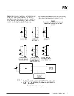
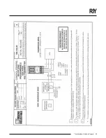
Figure 9.
RIY Installation Hookup Diagram
Figure 9 is an installation hookup diagram showing
the connections necessary to operate the RIY.
NOTE
It is strongly recommend that you use
shielded, twisted wire for low-level
signals.
1
2
3
4
4-WIRE RTD
1
2
3
4
3-WIRE RTD
(SEE NOTE 1)
1
2
3
4
2-WIRE RTD
1
2
3
4
DUAL SENSOR:
NO LEAD LENGTH
COMPENSATION
1
2
3
4
DUAL SENSOR:
NO LEAD LENGTH
COMPENSATION
(SEE NOTES 1 & 2)
1
2
3
4
TRIPLE SENSOR:
NO LEAD LENGTH
COMPENSATION
RIY
1
2
3
4
+PS
–PS
+
–
12-42 VDC
POWER
SOURCE
+
–
NOTES:
1. For 3-wire RTD's and dual sensors with lead length compensation, all leads
should be of the same gauge and length, and kept at the same temperature.
2. The single lead length compensation wire used for dual sensor hookups is
effective for both sensors.
CURRENT
DRIVEN
DEVICE
RTD


