background image

Owner’s Manual 


Rear Panel Connections 


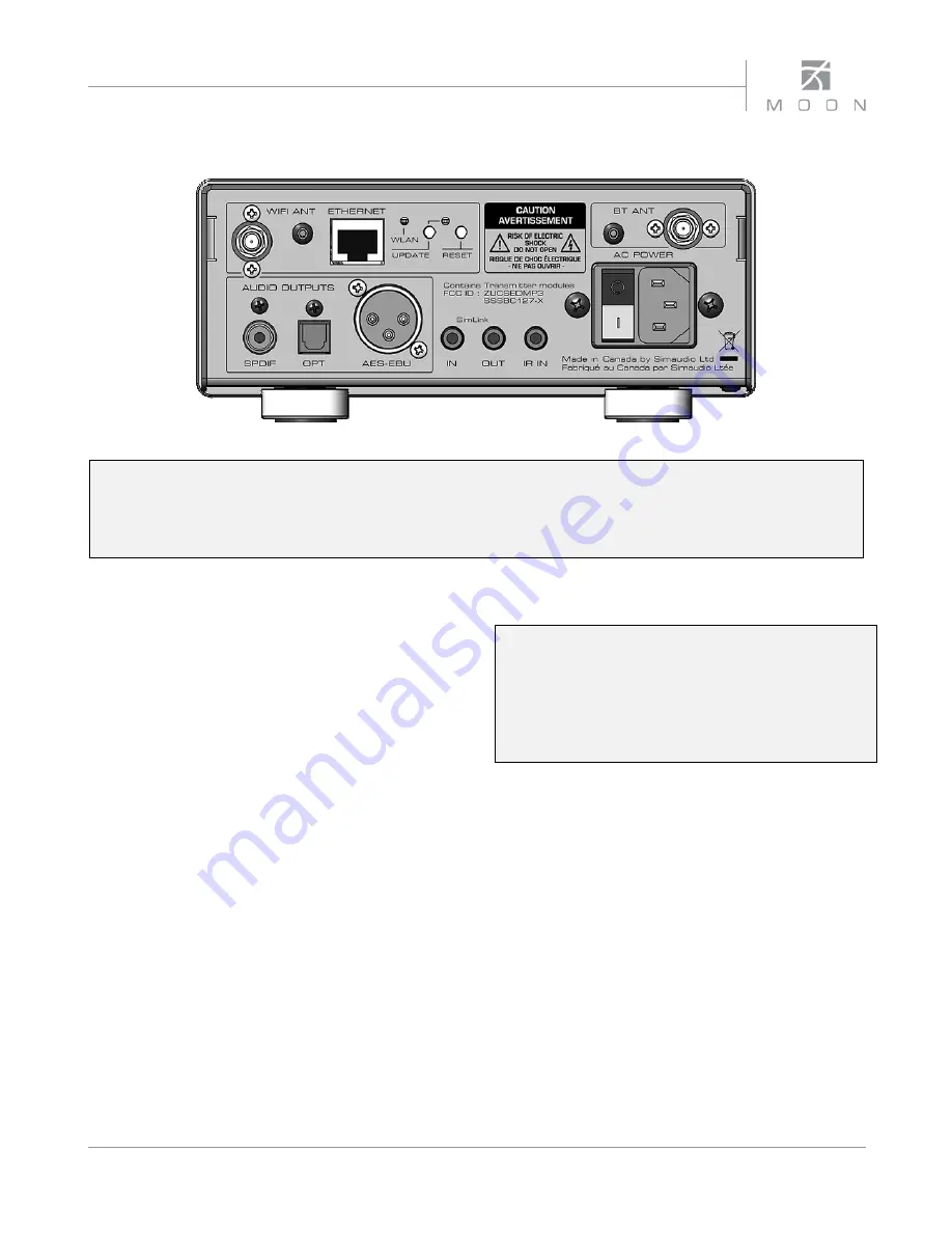
Figure 2: Nēo MiND Rear panel 


The rear panel will look similar to Figure 2 (above). The top left section is where you will find two MiND module 
inputs: “WIFI ANT” for a wifi antenna socket and “ETHERNET” for a RJ45 ethernet cable. This is followed by the WLAN 
status LED, a receded “UPDATE” button with a corresponding LED for MiND firmware updates (refer to Appendix B) 
and a receded “RESET” button for the hardware reset function (refer to Appendix C). The top right section is where 
you will find the socket for the blutooth antenna. 


There are three (3) Digital “Audio Outputs” as follows: A 
SPDIF output on an RCA connector which will benefit 
most from cables with an impedance of 75

Ω

; An optical 

output using Toslink connectors labelled “OPT” ; and 
finally a 3-pin XLR connector for an AES/EBU output 
which will benefit most from a cable with an impedance 
of 110

Ω

. Don’t hesitate to use high quality digital 

interconnect cables

*

.     


The right side of the rear panel has various connectors 
for external communications. The 

Nēo MiND

 is 

equipped with  two (2) “SimLink™” connectors labeled 
“in” and “out” on 1/8” mini jacks. Please refer to the next 
section entitled SimLink™ for more details.  Next, there’s 
a 1/8” mini-jack input, labelled “IR IN”, for use with 
aftermarket infrared remote control receivers. 


On the far right side is the main power switch (“0”=off, 
“1”=on) and the IEC receptacle, labeled “AC Input” for 
the included AC power cord. Connect the supplied AC 
power cable to the IEC receptacle. Ensure that the AC 
wall outlet you use has a functioning ground.  For the 
best sonic performance, it is preferable that you plug 
your 

Nēo MiND

 directly into a dedicated AC outlet and 

avoid using an extension cord. 


Please speak with your MOON Authorized Retailer about the 

benefits of high quality cables for your system

.


SimLink™ 


One of the main features of SimLink™ on the 

Nēo MiND

involves the “Standby” function. By pressing down and 
holding the “Standby” button for 2 seconds on the 

Nēo 

MiND

, all other 

MOON

 components connected via the 

SimLink will go into “Standby” mode along with the 

Nēo MiND.

 The same logic applies when switching 

from “Standby” to active mode.  


SimLink™ offers many features:, Mute, Standby, Digital 
input selection, and volume adjustments (with MOON 
preamplifiers and integrated amplifiers) all via the 
“MiND” app running on your Apple or Android device. 
 
If you are using either the Nēo 340i Integrated Amplifier 
with the DAC option or the Nēo 350P Preamplifier with 
the DAC option, you should make a SimLink™ 
connection between the MiND’s SimLink™ out and the 
340i / 350P SimLink™ in. When you press the 

X

 (play) 

button on the “MiND” App, the 340i / 350P will 
automatically switch to the digital input that you 
defined as the MiND input. As well, you can use the 
MiND App’s volume up, volume down and mute 
functions to adjust the volume level on 340i / 350P.

Summary of Contents for mind neo series

Page 1: ...Streaming Network Music Player Owner s Manual MiND Series...

Page 2: ...MiND N o Series...

Page 3: ...tripod bracket or table specified by the manufacturer or sold with the apparatus When a cart is used use caution when moving the cart apparatus combination to avoid injury from tip over 13 Unplug thi...

Page 4: ...the proper voltage Both the shipping box and rear panel serial number label will indicate the correct voltage Use of any other voltage will likely damage the unit and void the warranty 3 AC extension...

Page 5: ...ar Panel Connections 9 SimLink 9 Operating the N o MiND 10 Remote Control Operation 11 Specifications 13 Appendix A Setup Guide 14 Appendix B Firmware Update Procedure 17 Appendix C Hardware Reset Pro...

Page 6: ...al is subject to change without notice The most current version of this manual is available on our official website at http www simaudio com Your N o MiND Streaming Network Music Player incorporates m...

Page 7: ...al damage during transit Please write the serial number of your new N o MiND in the space provided below for future reference Serial Number Installation Placement The N o MiND requires only minimal ve...

Page 8: ...s the BT button and the corresponding BT LED will begin to blink continuously until pairing between your smart device and the N o MiND is successful or the 30 second time limit has been exceeded When...

Page 9: ...side is the main power switch 0 off 1 on and the IEC receptacle labeled AC Input for the included AC power cord Connect the supplied AC power cable to the IEC receptacle Ensure that the AC wall outle...

Page 10: ...rther details Operating the MiND We recommend leaving your N o MiND powered up at all times to maintain optimal performance When you plan on being away for a few days it may not be a bad idea to power...

Page 11: ...his button results in only a single change to the selected input The MUTE button turns off the output volume Pressing the Mute button a second time will reinstate the output volume level back to its c...

Page 12: ...put that is connected tp the MiND To shut down the system press Off for this ZONE in the MiND app Figure 5 Remote Operation with SimLink and 12 V Trigger In figure 5 we have a N o MiND connected to a...

Page 13: ...terface Bluetooth with Qualcomm aptXTM audio support Digital Outputs 3 AES EBU S PDIF and TosLink Encryption support WEP WPA and WPA2 wifi Remote Control Full Function CRM 3 Power Consumption idle 10...

Page 14: ...etwork the router acts as the hub for the entire network The main reason why it is mandatory that your router be wifi capable is for the tablet Apple or Android to communicate and control the N o MiND...

Page 15: ...nit s specific MAC address You can change the name in the network settings described below Regarding other features of the app please consult the MiND App User Guide available on the MiND page of our...

Page 16: ...8 Under Wireless enter the SSID the default is either blank or MiND remove whatever is there and type in your SSID 9 Select the security type your network is set up for 10 Enter your passphrase 11 Ta...

Page 17: ...ght side of the ETHERNET cable input This will require a small pin since the button is slightly recessed behind the rear panel 4 While still holding the UPDATE button 2 power up the N o MiND using the...

Page 18: ...he paperclip properly and push on the switch you ll feel it click Hold the switch down do not remove the paperclip until after step 4 4 While the Reset switch is pressed down power up the N o MiND usi...

Reviews: