moog
MSD Servo Drive DC-AC Operation Manual
[
]
Appendix
Application expample
83
Id.-No.: CA97554-001 Date: 06/2012
C Application example
C.1 Power supply unit/DC-AC servo drive
lock
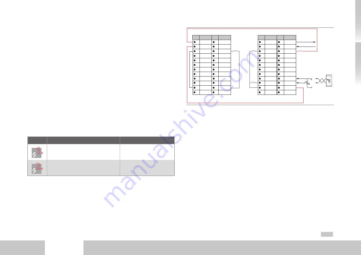
The following example presents a means of configuring the MSD Power Supply Unit
with the MSD Servo Drive DC-AC used in the multi-axis system such that in the event of
a fault the complete multi-axis system is shut down.
Normally in regenerative mode the DC-AC servo drives feed power back via the power
supply unit into the public grid. In the event of failure of the power supply unit or of the
public grid, the power is routed into the braking resistor. To protect against overloading
of the braking chopper of the power supply unit, the power supply unit can be config-
ured in conjunction with the DC-AC servo drives as follows. As soon as the power supply
unit is no longer actively controlling, the DC-AC servo drives' power stage enable (ENPO)
is cancelled.
Step
Action
Comment
1.
Wire the supply unit with the connected
DC-AC servo drives as shown in fig. C.1.
2.
Assign power supply unit output REL
(X4/23.24) the "Control in function" function
(value 2, OUTPUT_FS_ACTIV).
For more functions refer to the
MSD Power Supply Unit
Operation Manual.
24
23
22
21
20
19
18
17
16
15
14
13
12
11
10
9
8
7
6
5
4
3
2
1
REL
REL
ISDSH
ISD06
ISD05
ISD04
ISD03
ISD02
ISD01
ISD00
+24 V
DGND
RSH
RSH
ENPO
OSD02
OSD01
OSD00
ISA1-
ISA1+
ISA0-
ISA0+
+24 V
DGND
Des.
Des.
X4
X4
24
23
22
21
20
19
18
17
16
15
14
13
12
11
10
9
8
7
6
5
4
3
2
1
REL
REL
ISDSH
ISD06
ISD05
ISD04
ISD03
ISD02
ISD01
ISD00
+24 V
DGND
RSH
RSH
ENPO
OSD02
OSD01
OSD00
ISA1-
ISA1+
ISA0-
ISA0+
+24 V
DGND
Des.
MSD Power Supply Unit
MSD Servo Drive DC-AC
Des.
X4
X4
ENPO
Request
STO
Start
Request STO
Diagnosis STO
ISA0-
+10 V
ISA0+
ISA0-
ISA0+
CNC
or
PLC
Fig. C.1 MSD Servo Drive multi-axis system lock


