31
MSD Single-Axis Servo Drive Compact Operation Manual
ID no.: CA97555-001 Date:
04
/201
8
moog
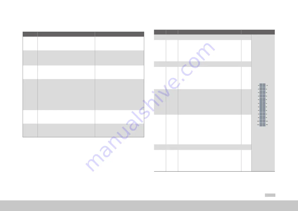
4.9.1
Specification of cont ol connections
Des.
Term.
Specification
Electrical isolation
Analog inputs
REL
REL
ISDSH
ISD06
ISD05
ISD04
ISD03
ISD02
ISD01
ISD00
+24V
DGND
RSH
RSH
ENPO
OSD02
OSD01
OSD00
ISA1-
ISA1+
ISA0-
ISA0+
+24V
DGND
24
23
22
21
20
19
18
17
16
15
14
13
12
11
10
9
8
7
6
5
4
3
2
1
X4
ISA0+
ISA0-
ISA1+
ISA1-
X4/3
X4/4
X4/5
X4/6
•
U
IN
= ±10 V DC
•
Resolution 12 bits; R
IN
approx. 101 kΩ
•
T
erminal scan cycle in "IP mode" = 125 µs,
otherwise
= 1 ms
•
Tolerance:
U ±1 % of the measuring range end value
no
Digital inputs
ISD00
ISD01
ISD02
ISD03
ISD04
X4/15
X4/16
X4/17
X4/18
X4/19
•
Frequency range <500 Hz
•
T
erminal scan cycle in = 1 ms
•
Switching level Low/High:
≤4.8 V / ≥18 V
•
U
IN max
= +24 V DC +20 %
•
I
IN
at +24 V DC = typ. 3 mA
yes
ISD05
ISD06
X4/20
X4/21
•
Frequency range ≤500 kHz
•
Switching level Low/High:
≤4.8 V / ≥18 V
•
U
IN max
= +24 V DC +20 %
•
I
IN max
max at +24 V DC = 10 mA,
R
IN
approx.
3 kΩ
•
Internal signal delay < 2 µs suitable as trigger input for
quickly saving actual position
yes
ENPO
X4/10
•
Disable restart inhibit (STO) and enable power stage =
High level
•
OSSD support
•
10 ms
•
Switching level Low/High:
≤4.8 V / ≥18 V
•
U
IN max
= +24 V DC +20 %
•
I
IN
at +24 V DC = typ. 3 mA
yes
Digital outputs
OSD00
OSD01
OSD02
X4/7
X4/8
X4/9
•
No destruction in case of short-circuit (+24 V DC ->
DGND), but device may briefly shut down
•
I
max
= 50 mA,
PLC-compatible
•
T
erminal scan cycle in = 1 ms
•
High-side driver
yes
Table 4.7 Specification of control connections X4
4.9 Control connections
Step
Action
Comment
1.
Check whether complete device settings are already
available, i.e. whether the drive has already been
configured
2.
If this is the case, a special control terminal assign-
ment applies.
Please contact your project engineer to obtain the
terminal assignment!
3.
Choose a terminal assignment.
Initial commissioning
4.
Wire the control terminals with shielded cables.
The following is imperative: STO request X4/22,
ENPO X4/10 and a start signal (with control via
terminal).
Earth the cable shields over a large area at
both ends.
Rigid conductor sizes: 0.2 to 1.5 mm²
(0.0003 to 0.0023 in²)
Flexible conductor sizes:
- Ferrule without plastic sleeve:
0.2 to 1.5 mm² (0.0003 to 0.0023 in²)
- Ferrule with plastic sleeve:
0.2 to 0.75 mm² (0.0003 to 0.0012 in²)
5.
Keep all contacts open (inputs inactive).
6.
Check all connections again!
Continue with chapter “5 Commissioning”
Note the following points:
y
Always wire the control terminals with shielded cables.
y
Lay the control cables separately from the mains power and motor cables.
y
A cable type with double copper braiding,
with 60 to 70 % coverage,
must be used for all
shielded connections.
Summary of Contents for MSD C2
Page 8: ...8 MSD Single Axis Servo Drive Compact Operation Manual ID no CA97555 001 Date 04 2018 moog ...
Page 16: ...16 MSD Single Axis Servo Drive Compact Operation Manual ID no CA97555 001 Date 04 2018 moog ...
Page 44: ...44 MSD Single Axis Servo Drive Compact Operation Manual ID no CA97555 001 Date 04 2018 moog ...
Page 54: ...54 MSD Single Axis Servo Drive Compact Operation Manual ID no CA97555 001 Date 04 2018 moog ...
Page 66: ...66 MSD Single Axis Servo Drive Compact Operation Manual ID no CA97555 001 Date 04 2018 moog ...
Page 71: ...71 MSD Single Axis Servo Drive Compact Operation Manual ID no CA97555 001 Date 04 2018 moog ...


