MSD Multi-Axis System Operation Manual DC-AC Servo Drive
moog
Id. no.: CA97554-001 0
5
/2017
85
10 Application example
10 Application example
10.1 Interlocking Power Supply Unit and
DC-AC Servo Drives
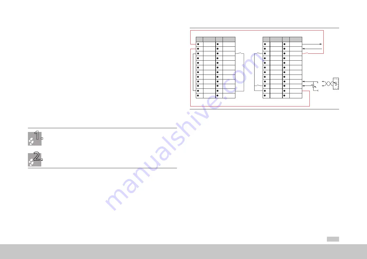
The following example shows how the Power Supply Unit can be connected to the
DC-AC Servo Drives used in the multi-axis system such that the entire multi-axis system
is shut down in the event of a fault.
In the normal case the DC-AC Servo Drives feed power back to the mains via the Power
Supply Unit in regenerative operation. On the failure of the Power Supply Unit or the
mains, the energy is fed to the braking resistor. To protect against overloading the Power
Supply Unit's brake chopper, the Power Supply Unit can be connected to the DC-AC
Servo Drives and configu ed as follows. As soon as the Power Supply Unit is no longer
actively regulated, the enable for the power stage (ENPO) is withdrawn from the
DC-AC Servo Drives.
Connect the Power Supply Unit to the DC-AC Servo Drives connected as shown in Figure 10.1.
Assign the output REL (X4/23,24) on the Power Supply Unit the function "Regulation in operation"
(value 2, OUTPUT_FS_ACTIV).
You will find further functions in the Operation Manual MSD Power Supply Unit.
1.
2.
24
23
22
21
20
19
18
17
16
15
14
13
12
11
10
9
8
7
6
5
4
3
2
1
REL
REL
ISDSH
ISD06
ISD05
ISD04
ISD03
ISD02
ISD01
ISD00
+24 V
DGND
RSH
RSH
ENPO
OSD02
OSD01
OSD00
ISA1-
ISA1+
ISA0-
ISA0+
+24 V
DGND
Des.
Des.
X4
X4
24
23
22
21
20
19
18
17
16
15
14
13
12
11
10
9
8
7
6
5
4
3
2
1
REL
REL
ISDSH
ISD06
ISD05
ISD04
ISD03
ISD02
ISD01
ISD00
+24 V
DGND
RSH
RSH
ENPO
OSD02
OSD01
OSD00
ISA1-
ISA1+
ISA0-
ISA0+
+24 V
DGND
Des.
MSD PSU
MSD Servo Drive DC-AC
Des.
X4
X4
ENPO
Request
STO
Start
Request STO
Diagnostic STO
ISA0-
+10 V
ISA0+
ISA0-
ISA0+
CNC
or
PLC
Figure 10.1 Interlocking MSD Multi-axis system


