Moog Videolarm WARRIOR 1 Product Instructions Download Page 2

- 2 -

CAMERA BRACKET SETUP

Once the housing is installed, the three axis camera bracket allows 

the camera to be adjusted to the desired viewing location and angle 

(Figure 6, next page).

IMPORTANT:

A sticker has been placed on top of the lens holder of

                        the camera to help in orienting the unit correctly.   

Figure 3

1.  Connect the output of your Class 2 Power Supply to the terminal 
     connectors on the PC Board inside the housing.  Refer to the 
     Troubleshooting section later in this instruction sheet for more 
     information. 

2.

  Connect the incoming video cable to the BNC connector. 

NOTE:

  For NVT Twisted Pair see Addendum 1, for IFS Fiber 

                  see Addendum 2.

Terminal Connector

Positive

Negative

NOTE:

The following instructions are for camera bracket setup, 

             camera focusing, and camera set-up. 

7KH¿QDOVWHSVIRULQVWDOODWLRQIROORZWKHVHVHFWLRQV

Use Class 2 Power only. Input voltage must be 

                   between 12-28 VDC or 15-28 VAC.
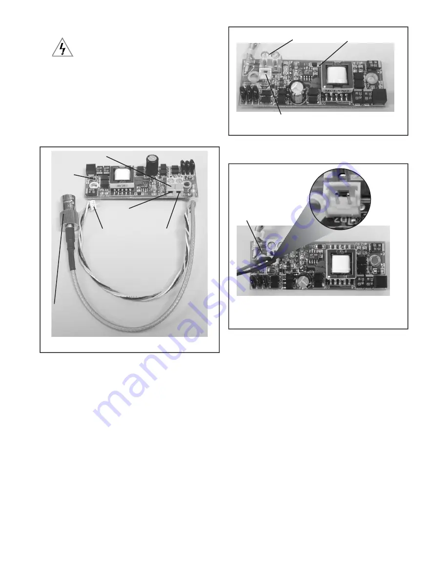
WIRING (Figure 3)

Connected to 
the Camera

Connect to 
incoming video 
BNC

Power
Board

DESCRIPTION

The Warrior Test Monitor Cable is a tool that allows users to 
view video from cameras via a small on-site monitor. It's quick 
and easy to use.

1.

  Using the security tool provided, loosen the four security 

     fasteners and remove the housing top.

NOTE:

  The housing 

     top is held to the base by a lanyard. 

2.  Locate the power board on the inside of the housing. The Test
     Monitor Cable plug is located beside the terminal block where
     incoming power is connected (Figure 4).

Figure 4

Power Board

Terminal Connector

Test Monitor Cable plug

3.

  Plug the test monitor cable into the power board (Figure 5).

     Attach the BNC connector to your test monitor. 

Test Monitor Cable (NOTE: Your cable may look different)

Figure 5

The plug for the Test 
Monitor Cable is polarity 
protected and can only 
be inserted one way.

OPTIONAL WARRIOR TEST MONITOR CABLE
(Part # - WSTMC)

Summary of Contents for WARRIOR 1

Page 1: ...K XVLQJ D DW KHDG VFUHZGULYHU B Use the 3 4 conduit plug to cover the 3 4 threaded hole To do this loosen the 6 32 set screw that holds the connector in remove the connector and replace it with the pl...

Page 2: ...H VHFWLRQV Use Class 2 Power only Input voltage must be between 12 28 VDC or 15 28 VAC WIRING Figure 3 Connected to the Camera Connect to incoming video BNC Power Board DESCRIPTION The Warrior Test Mo...

Page 3: ...an also be adjusted up and down if needed Retighten the thumb screws 127 8VH RFWLWH RU DQ HTXLYDOHQW SURGXFW WR VHFXUH WKH WKXPE screws especially where vibration is a concern Rotating Bracket CAMERA...

Page 4: ...tch UP DOWN 1 Iris Auto Iris On Position for Fixed Lens 2 Flickerless Shutter speed Normal HG DW VHF 3 Back Light ON Normal Compensation 4 Synch Mode Internal Synch Line Lock Mode SERIAL NUMBERS BEGIN...

Page 5: ...K 6 DO NOT send Up the Coax Pan Tilt Zoom signals through active amplified NVT transceivers Measure your wire distance Note All NVT quoted distance specifications include any coax in the run It is rec...

Page 6: ...000 m 1200 m 1500 m 1800 m 2400 m 75 m 100 m 125 m 150 m 200 m 300 m 400 m 500 m 600 m 750 m 900 m 1000 m 1200 m 1500 m 1800 m 2400 m 3 5 6 9 13 4 7 9 12 18 6 8 11 15 22 7 10 13 18 27 9 13 17 24 36 13...

Page 7: ...appear to be unusually dim STATIONARY OR SCROLLING HORIZONTAL LINES ON SCREEN PICTURE IS CLEAR LOW OR NO COLOR PICTURE IS DARK OR GRAINY IN GOOD LIGHTING CONDITIONS The auto iris lens is set at the fa...

Page 8: ...k polarity WON T SYNC TORN PICTURE 1 Make sure that you are using unshielded twisted pair wire 2 Check distance equalization settings 3 For installations with passive non amplified transceivers at bot...

Page 9: ...4 VAC 202mA 4 8W CABLE AND POWER GUIDELINES This chart shows the proper current needed for power supplies for Warrior Series cameras Use Class 2 Power only Input voltage must be between 12 28 VDC or 1...

Page 10: ...1 2 3 4 5 6 7 10 WS1 Exploded Diagram...

Page 11: ...KIT 486 PAL BOARD CAMERAS RPWS1041PF WARRIOR 1 2 PAL STANDARD RES BLACK WHITE FIXED CAMERA KIT 144 RPWS1041PV WARRIOR 1 2 PAL STANDARD RES BLACK WHITE VARIFOCAL CAMERA KIT 228 RPWS1043PF WARRIOR 1 2...

Page 12: ...1 2 4 6 7 8 3 5 12 WS3 Exploded Diagram...

Page 13: ...KIT 370 RPWS3046A WARRIOR 3 4 ULTRA HI RES COLOR AUTO IRIS VARIFOCAL CAMERA KIT 486 PAL BOARD CAMERAS RPWS3041PF WARRIOR 3 4 PAL STANDARD RES BLACK WHITE FIXED CAMERA KIT 144 RPWS3041PV WARRIOR 3 4 PA...

Page 14: ...charges The limited warranty stated in these product instructions is subject to all of the following terms and conditions 1 NOTIFICATION OF CLAIMS WARRANTY SERVICE If Purchaser believes that the Prod...

Reviews: