Moog Videolarm FDW8CS Manual Download Page 4

-4 -

dIsPLAY - 

This controls the display of the compass heading and 

allows the user to calibrate the compass heading. PAN RIGHT to 
access the sub-menu. TILT DOWN to access each item. PAN LEFT 
to return to the main menu.

     sHoW

 - Allows the title to be displayed. Press "zoom in" to

     turn this on, "zoom out" to turn it off.

     PrIVAtE

 - Determines if this will be a privacy zone. Press "zoom 

     in" to turn this on, "zoom out" to turn it off.

     rLIMIt

 - Sets the pan right limit for the zone. The current pan 

limit 
     will be displayed. Press "zoom out", the picture will reappear and 
     you will have pan control. Pan to the desired location. Press 
"zoom 
     in" to select. The new pan limit will appear. 

     LLIMIt

 - Sets the pan left limit for the zone. The current pan limit 

     will be displayed. Press "zoom out", the picture will reappear and 
     you will have pan control. Pan to the desired location. Press 
"zoom 
     in" to select. The new pan limit will appear. 

     NOTE: The picture will displayed whenever you are in RLIMIT  

     coMPAss

 - The display show “COMPASS ON” or “COMPASS 

     OFF”. Press “zoom in” to turn the compass heading on and 
“zoom 
     out’ to turn the compass display off.

     sEt nortH

 - Press “zoom in” button to set calibration. The 

     display will show “OK”.

     PosItIon

 - This displays the pan and tilt positions of the cam-

era. 
     Press "zoom in" to turn this on, "zoom out" to turn it off.

     AddrEss

 - This displays the camera address. Press "zoom in" 

to    
     turn this on, "zoom out" to turn it off.

     tEMP

 - This displays the temperature sensor data on the tilt 

     board. Press "zoom in" to turn this on, "zoom out" to turn it off. 
         

notE:

 This reading will be higher than the actual ambient 

         temperature in the dome. This is for diagnostic use only. 

cAMErA - 

The “CAMERA” sub-menu is used to control several of 

the camera’s parameters. PAN RIGHT to access the sub-menu. TILT 
DOWN to access each item. 

     notE: 

When this sub menu is accessed the camera picture will    

                 return to allow adjustments.

     STABILIZER

 - Stabilizer, where equipped,  compensates for 

small
     movements or vibrations when the camera is “zoomed in”. Press 
     "zoom in" to turn this on, "zoom out" to turn it off.


DAY/NIGHT

 - This is used to control the low light mode of the 

     camera. There are three choices:
          AUTO - The camera will automatically switch into day/night 
                       mode for low light conditions.
          DAY - The camera will be in the day mode continuously.
          NIGHT - The camera will be in the night mode continuously.
     Press "zoom in" to cycle through the choices. P

     sHuttEr

 - Selects between auto and manual shutter speeds. 

     Press "zoom in" to cycle up through the selections, or "zoom out" 
     to cycle down.

     BAcKLIGHt

 - Controls backlight compensation. Press "zoom in"

     to turn this on, "zoom out" to turn it off. 

     AGc

 - Selects automatic AGC or minimum AGC (0db). Press 

     "zoom in" to turn this on, "zoom out" to turn it off.

     DIGI ZOOM

 - Turns the digital zoom on and off. Press "zoom in" 

to

ALArM - 

To get to this section, tilt down from the CAMERA menu. 

This menu allows the user to control the operation of the alarm input. 
If the alarm is enabled, the camera will go to preset 1. Press "zoom 
in" to enable, press "zoom out" to disable.
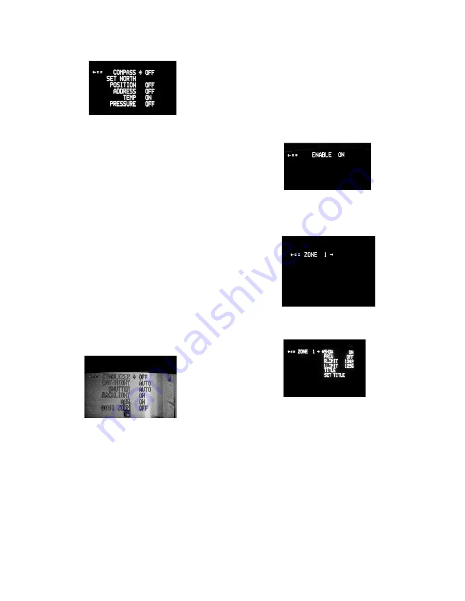
ZONES - 

Up to 16 zones may be selected, each zone has a number 

of parameters associated with it.  Pan Right to access Zones. 
"ZONE 1" will display. 

"Tilt up" or "Tilt down" to select the zone desired. Once the zone is 
selected, "Pan Right" to access the sub-menu.

Summary of Contents for FDW8CS

Page 1: ...iver 1 FDW8CS A wall mount bracket comes standard with this unit and a template is included to use as a guide for mounting the bracket to a wall Choose the desired location for installation mark and drill holes using the template Run approximately 8 of wiring out of the wall 2 Open the access door on the bottom of the wall mount by loosening the screw nearest the mounting plate Figure 1 3 Run the ...

Page 2: ...g to temporarily hold it while making wiring connections Loop the safety cable over one of the set screws on the housing coupling and make the appropriate connections using the 2 screw down connectors supplied 2 Undo the safety cable and twist the housing onto the housing coupling Secure all 3 setscrews provided on the housing coupling Figure 3 3 Clean the outside of the dome 1 Camera Power 24 VAC...

Page 3: ...rt Auto Tour 80 GO TO Run Pattern 80 SET Start Recording Pattern 81 SET Stop Recording Pattern 89 GO TO Put Camera Into Auto Iris Mode 95 GO TO Display Main Menu The FDW8CS is setup with 2 individual power inputs 1 Accessory Power yellow and green wire 2 Camera Power red and orange If you wish to provide a single power transformer 1 Be certain that you know the total power consumption of the hous ...

Page 4: ... reading will be higher than the actual ambient temperature in the dome This is for diagnostic use only CAMERA The CAMERA sub menu is used to control several of the camera s parameters PAN RIGHT to access the sub menu TILT DOWN to access each item NOTE When this sub menu is accessed the camera picture will return to allow adjustments STABILIZER Stabilizer where equipped compensates for small movem...

Page 5: ... there is an error in communicating with the camera DIPSWITCH SETTINGS Address Dip switch settings refer to Table 1 on next page SYSTEM INFO Displays the Pan Version Tilt Version Current Pan Position and Current Tilt Position PRESETS Allows the selection of the dwell times for each of the 64 presets When this submenu is selected the dwell time for each of the 64 presets is displayed NOTE If a pres...

Page 6: ...154 ON OFF OFF ON ON OFF ON OFF 155 ON OFF OFF ON ON OFF ON ON 156 ON OFF OFF ON ON ON OFF OFF 157 ON OFF OFF ON ON ON OFF ON 158 ON OFF OFF ON ON ON ON OFF 159 ON OFF OFF ON ON ON ON ON 160 ON OFF ON OFF OFF OFF OFF OFF 161 ON OFF ON OFF OFF OFF OFF ON 162 ON OFF ON OFF OFF OFF ON OFF 163 ON OFF ON OFF OFF OFF ON ON 164 ON OFF ON OFF OFF ON OFF OFF 165 ON OFF ON OFF OFF ON OFF ON 166 ON OFF ON OF...

Page 7: ... OFF OFF 149 ON OFF OFF ON OFF ON OFF ON 150 ON OFF OFF ON OFF ON ON OFF 151 ON OFF OFF ON OFF ON ON ON 145 ON OFF OFF ON OFF OFF OFF ON 146 ON OFF OFF ON OFF OFF ON OFF 147 ON OFF OFF ON OFF OFF ON ON 148 ON OFF OFF ON OFF ON OFF OFF 149 ON OFF OFF ON OFF ON OFF ON 150 ON OFF OFF ON OFF ON ON OFF 151 ON OFF OFF ON OFF ON ON ON 152 ON OFF OFF ON ON OFF OFF OFF 153 ON OFF OFF ON ON OFF OFF ON 154 O...

Page 8: ...SW4 SW3 SW2 SW1 225 ON ON ON OFF OFF OFF OFF ON 226 ON ON ON OFF OFF OFF ON OFF 227 ON ON ON OFF OFF OFF ON ON 228 ON ON ON OFF OFF ON OFF OFF 229 ON ON ON OFF OFF ON OFF ON 230 ON ON ON OFF OFF ON ON OFF 231 ON ON ON OFF OFF ON ON ON 232 ON ON ON OFF ON OFF OFF OFF 233 ON ON ON OFF ON OFF OFF ON 234 ON ON ON OFF ON OFF ON OFF 235 ON ON ON OFF ON OFF ON ON 236 ON ON ON OFF ON ON OFF OFF 237 ON ON ...

Page 9: ...port Ring 30 VL1695 1 4 25W 24VAC w Leads 72 HT1752 1 5 FD8 Clear Dome 20 DCFD8 1 n s FD8 Tinted Dome 20 DTFD8 1 n s 9 25 O ring 96 RSORG11 2 6 Plastic Ring Plugs 30 VL1696 6 7 FD8 PCB 76 FPD8PB 1 8 FD8 Upper Housing Bracket 30 VL1744 1 9 Housing Gasket 96 PSGK05 3 10 Housing Fan 71 VLBL03 1 11 Adapter Bracket In Housing Packet 40 PKFD8 1 12 1 4 x 20 x 75 HH Bolts 90 BTHH27 4 12 1 4 Split Lock Was...

Page 10: ... charges The limited warranty stated in these product instructions is subject to all of the following terms and conditions 1 NOTIFICATION OF CLAIMS WARRANTY SERVICE If Purchaser believes that the Product is defective in material or workmanship then written notice with an explanation of the claim shall be given promptly by Purchaser to Videolarm but all claims for warranty service must be made with...

Page 11: ...2 000 3 250 R 733 2 132 2 981 1 537 5 500 11 Mounting Template ...

Reviews: