background image

Page 1

ME38-ODV-2 Homefire

Part No. XG0123

Installation

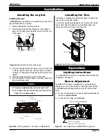
Installing the Log Set

Installing the Logs:

The 

ME38-ODV-2 

is supplied with six ceramic fibre logs. Unpack the 

logs and handle them very carefully. 

1.

  Remove the door cover and the glass door.

2.

  Place the Back log onto the back log rest as shown below in 

figure 24a. The log has lip on the bottom which fits into the slot 
on the log rest.

Figure 24a. 

Positioning for the front and back logs.

Log 'D'

Log 'E'

Log 'A'

3.

  Place the Front log onto the front log rest as shown in figure 24a. 

Center the log from side to side, and push it against the back of 
the log rest. Carefully push the log onto the metal spikes on the 
log rest.

4.

  Place the top logs in position as shown in figure 24b.

5.

  Start the fireplace. If the flame appears satisfactory, replace the 

glass door and door cover.

NOTES

:


If logs are not placed properly, excessive sooting will result.

  The  surface  of  the  logs  will  crack  due  to  the  heat  from  the 

flames. This is a normal occurance.

Log 'C'

Log 'B'

Figure 24b.

 Proper log placement . (No embers on ME38-ODV2) 

Figure 25.

  Installing the horizontal trim pieces.

Installing the Trim

The fireplace is shipped with 6 horizontal trim pieces (3 upper and 3 
lower), which must be field-installed. 
Install the trim by placing the top edge of the trim over to the retainer 
clips on either side of the fireplace. Push the bottom edge firmly 
inwards and the trim will snap on. 

(See figure 25)

Operation

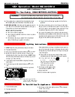
Lighting Instructions

It is recommended that the burner is inspected each time beforeusing 
this appliance. See page 14.

Burner Adjustment

The ME38-ODV-2 fireplace is equipped with an adjustable burner, 
allowing you to raise or lower the flames. Operating the control knob 
as described below will adjust both the main burner and the ember 
burner.

  To raise the flame height, turn the black knob (located behind the 

lower trim) 

counterclockwise

.

  To lower the flame height, turn 

clockwise

.

Gas Control Knob

(Shown in "Pilot" postion.)

'Hi-Lo' Adjustment Knob

Figure 26.


'Hi-Lo' Adjustment on the ME38-ODV-2's gas valve.

Summary of Contents for Homefire ME38-ODV-2

Page 1: ...neighbor s phone Follow the gas supplier s instructions If you cannot reach your gas supplier call the fire department For Your Safety Do not store or use gasolineorotherflammable vapors and liquids in the vicinity of this or any other appliance Safety Notice Glass doors on gas fireplaces are extremely hot while the fireplaces is on and remain hot even after the fireplace has been turned off Safet...

Page 2: ...s Installations in the USA must conform to local codes or in the absense of local codes to the National Fuel Gas Code ANSI Z223 1 1988 If the optional air circulating fan is installed it must be ground ed in accordance with local codes or in the absence of local codes with the National Electrical Code ANSI NFPA 70 1987 Table Of Contents Introduction 2 Installation Installing the Fireplace Shell 3 ...

Page 3: ...ay be reduced to 14 3 4 37 3 4 15 1 2 40 3 4 43 7 8 24 1 8 0 clearance to corners only Framing WARNING When this appliance is installed directly on carpeting tile or any combustible material other than wood flooring it must be installed on a metal or wood panel extending the full width and depth of the appliance 14 3 4 28 3 4 34 3 4 Ø7 Ø4 14 3 4 38 33 Ø7 C Ø4 5 1 2 Top Vent Front View Rear Vent Cl...

Page 4: ...d be accessible for test gauge connection immediately upstream of the gas supply controls to the appliance The fireplace gas connection and the main operating gas valve is located behind the removable brass trim at the bottom of the unit and need only be attached to the gas line with an approved fitting as required by the applicable installation codes Installation Figure 6 Fireplace locations and ...

Page 5: ... Frame the termination opening to 12 x 12 2 Fasten the MOSR frame to the interior side of the studs using a minimum of 4 screws 3 Insert the termination into the MOSR frame as shown here and attach by screwing through the four pilot holes in the termination MSR MTO 3 MTO 3F MTO 3 MTKOG 1 Ensure that the two long mounting brackets are facing the bot tom of the termination See inset This will provid...

Page 6: ... from the floor of the fireplace is 72 and the horizontal run to the wall flange of the vent termination is 84 this would not be an accept able installation Figure 7 Venting Graph Figure 8 Heat Shield Install by sliding over the vent pipe where it passes through combustible construction Heat Shields Due to high flue temperatures heat shields are required on all 38 Series Modular Direct Vent instal...

Page 7: ...ted in opposite direction see Figure 10 and 11 D flex sections and E solid sections may be used in conjunction with one another to obtain different possible horizontal length instal lations NOTE Flex section with no vertical rise must not exceed maximum horizontal length of 3 feet see Figure 12 Flex runs over 3 feet must fall within the limits set by the venting graph and must have a minimum verti...

Page 8: ...when measured center to center of piping Example Typical vent installation 20 vertical vent 2 2 offsets required 25 of 20 5 max offset allowed This venting configuration meets requirements A Termination MVTK 1 B Flex sections MFL 1 12 section MFL 2 24 section MFL 3 36 section MFL 4 48 section C Solid sections MEXT 1 12 section MEXT 2 24 section MEXT 3 36 section MEXT 4 48 section D Support Ring Pl...

Page 9: ...ion The height from the hearth to the center of the termination is 28 ME38 ODV 2 Rear Vent versions are supplied with an 18 extension pipe EXT 18 with female female connections For shorter installations cut the EXT 18 to the desired length For extended installations use the EXT 18 section as supplied for an 18 vent run Note For Rear Vent models maximum horizontal run with no vertical lift must nev...

Page 10: ...on from the hearth is 90 and the horizontal run to the wall flange of the vent termination is 126 this would be an acceptable installation Example C Unacceptable Installation If the vertical dimension from the floor of the fireplace is 78 and the horizontal run to the wall flange of the vent termination is 108 this would not be an accept able installation Figure 18a ME38 ODV 2 Rear Vent Venting Gr...

Page 11: ...n allowed in shaded area 1 2 3 4 5 6 7 8 9 10 11 12 Figure 19a Combustible mantles and facings Mantels Surrounds NOTE National Canadian Gas Association mantel test requirements are for fire hazard prevention to combustible materials New technology to meet consumer and government demands for the wise use of energy has prompted us to manufacture many models of fireplaces which are hot fuel and energ...

Page 12: ... shell See Inset 2 Store the screws and clamps in a safe place to ensure that they are not lost To re install the insert simply reverse the steps above Figure 22 ME38 ODV 2 insert INSET 1 Tab INSET 2 Mounting Bracket Fresh Air Flex 4 dia High temp silicone seal Venting Plate Front Slot Installation Removing and Installing the Door Removing the Door Remove the trim as described on the next page to ...

Page 13: ...ogs will crack due to the heat from the flames This is a normal occurance Log C Log B Figure 24b Proper log placement No embers on ME38 ODV2 Figure 25 Installing the horizontal trim pieces Installing the Trim The fireplace is shipped with 6 horizontal trim pieces 3 upper and 3 lower which must be field installed Install the trim by placing the top edge of the trim over to the retainer clips on eit...

Page 14: ...del ME38 ODV 2 3 Push in gas control knob slightly and turn clockwise to Off Do not force 4 Flip up lower trim 1 Turn off remote switch 2 Flip down lower trim 1 STOP Read the safety information above on this label 2 Flip down lower trims 3 Push in gas control knob and turn clockwise to OFF 4 Wait five 5 minutes to clear out any gas Smell for gas including near the floor If you then smell gas STOP ...

Page 15: ...ny film which is a normal biproduct of combustion which may be visible Film can easily be removed by removing the door as shown on page 13 Handle the door carefully and clean it with non abrasive glass cleaners One of the most effective products is Kel Kem Silicone seals on inner door during initial firing will off gas leav ing a visual deposit of a white substance on combustion cham ber walls Thi...

Page 16: ...mponents not manufactured or supplied by The Companies 2 The Montigo Gas Appliance must be subjected to normal use The Gas Appliances are designed to burn gas only Burning conventional fireplace fuels such as wood coal or any other solid fuel will cause damage to the Gas Appliance will produce excessive temperatures and will result in a fire hazard Limitations On Liability It is expressly agreed a...

Page 17: ...the United States 6 feet 1 8 m minimum in Canada L clearance to nonmechanical air supply inlet to building or the combus tion air inlet to any other appliance 16 inches 41 cm minimum for appliances 100 000 BTU H 30kW M clearance to mechanical air supply inlet 6 feet 1 8 m minimum N clearance above paved sidewalk or a paved driveway located on public property 7 feet 2 1 m minimum P clearance under ...

Page 18: ...Canadian Heating Products Inc Langley BC V4W 4A1 Montigo Del Ray Corp Ferndale WA 98248 XG0123 011707 ...

Reviews: