background image


INSTALLATION AND OPERATION 


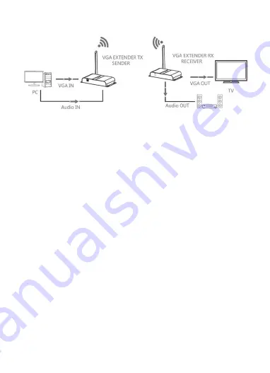
Perform the following steps to connect the BitPath AV™ system: 

1.


Place or mount the transmitter and receiver in their desired locations. 

2.


Position the antennas on each unit to a vertical position, then ensure the 
antenna connector is tight. 

3.


Using a VGA cable (not included), plug one end into the VGA input on your 
monitor, then plug the other end into the VGA Output (7) connector on the 
receiver. 

4.


Plug a pair of powered speakers, headphones, or an audio cable (not included) 
into the Audio Out (1) jack on the receiver. 

5.


Using a VGA cable (not included), plug one end into the VGA Input (7) connector 
on the transmitter, then plug the other end into the VGA output on your 
computer or other video source device. 

6.


Using the included 3.5mm Audio Cable, plug one end into the Audio In (1) jack on 
the transmitter, then plug the other end into the audio output jack on your 
computer or other video source device. 

7.


Plug the DC barrel connector on one of the AC power adapters into the DC In (2) 
jack on the receiver, then plug the adapter into a nearby AC power outlet. The 
Power LED (3) on the receiver will illuminate. 

8.


Plug the DC barrel connector on the other AC power adapter into the DC In (2) 
jack on the transmitter, then plug the adapter into a nearby AC power outlet. 
The Power LED (3) on the transmitter will illuminate. At the same time the Data 
Transmission LED (5) on both the transmitter and receiver will start flashing 

Summary of Contents for BitPath AV 16224

Page 1: ...MONOPRICE BitPath AV VGA Wireless Transmitter Receiver Kit 200m P N 16224 User s Manual...

Page 2: ...ratures Do not place it in on or near heat sources such as a fireplace stove radiator etc Do not leave it in direct sunlight Prior to operation check the units and power adapters for physical damage D...

Page 3: ...up to 656 feet 200 meters Supports VGA resolutions up to 1920x1080 60Hz Uses the BitPath AV transmission protocol CUSTOMER SERVICE The Monoprice Customer Service department is dedicated to ensuring th...

Page 4: ...ervice for a replacement 1x Transmitter 1x Receiver 2x AC Power Adapters 1x 3 5mm TRS Audio Cable 1x User s Manual PRODUCT OVERVIEW Transmitter 1 Audio In 3 5mm TRS jack for connecting analog audio fr...

Page 5: ...jack for connecting headphones powered speakers or an external amplifier 2 DC In DC barrel connector for attaching the included AC power adapter 3 Power LED Illuminates when power is applied 4 Reset...

Page 6: ...r on the transmitter then plug the other end into the VGA output on your computer or other video source device 6 Using the included 3 5mm Audio Cable plug one end into the Audio In 1 jack on the trans...

Page 7: ...transmitter and receiver are plugged in and that the Power LED 3 on each unit is illuminated Try swapping out the VGA cable with a known good one Q2 The monitor displays Please check the TX input sign...

Page 8: ...website www monoprice com during regular business hours 7 days a week You can also get assistance through email by sending a message to tech monoprice com SPECIFICATIONS Model 16224 Video Standard VGA...

Page 9: ...able protection against harmful interference in a commercial installation This equipment generates uses and can radiate radio frequency energy and if not installed and used in accordance with the inst...

Page 10: ...approved by Monoprice including the use of non approved antennas could void the user s authority to operate this device This device complies with IC RSS 210 Operation is subject to the following two c...

Reviews: