SR3 Type 1 Technical Manual
TSP005.doc Issue 5.0 – Jan 2005
Money Controls 2005. All rights reserved.
Page 27 of 50
18. Totaliser Mode
By connecting an additional ‘piggy back’ PCB to the SR3, (
Connector 5), totalising
functions are available. It is advisable to have the SR3 set-up in this mode if it is at all possible
that the totaliser function may be used.
If a totaliser PCB is not connected, the SR3 will function normally.
NOTE: If the totaliser is fitted, credits can be obtained from the totaliser output AND the
standard SR3 10 way interface simultaneously.
The totaliser board provides the following physical interface to the machine.
18.1 19 way Parallel Interface Connector
Table 11: 19 way Parallel Interface Connector
Pin No.
Function
I/P - O/P
1
No Function
2
No Function
3
No Function
4
No Function
5
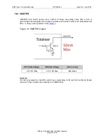
CMETER (Coin Meter)
O/P
6
No Function
7
No Function
8
V Supply 12V
9
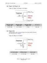
Player 1 HI
O/P
10
Player 1 LOW
O/P
11
No Pin
12
GND
13
Dispense 1
I/P
14
Player 2
O/P
15
Dispense 2
I/P
16
Player 3
O/P
17
Dispense 3
I/P
18
Player 4
O/P
19
Dispense 4
I/P
This connector provides all the control pins for totalising for up to 4 players including supply
voltages.


