background image

56D2161 

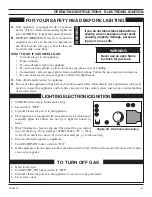
41

ON

OFF

PILOT

LO

HI

Figure 62 - Electronic Gas Valve 

OPERATING INSTRUCTIONS - ELECTRONIC IGNITION

  LIGHTING ELECTRONIC IGNITION  

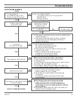
1.  STOP! Read the safety information above.
2.  Set switch to “OFF”.
3.  Turn off all electric power to the appliance. 
4.  This appliance is equipped with an ignition device which auto-

matically lights the burner. Do not try to light the burner by 
hand. 

5.  Wait 5 minutes to clear out any gas. Then smell for gas, includ-

ing near the floor. If you smell gas STOP! Follow “B” — 

What 

to Do if You Smell Gas 

above. If you do not smell gas, go to the next step.

6.  Turn on all electric power to appliance.
7.  Turn RS-OFF-ON rocker switch to “ON”. 
8.  If the appliance will not operate, follow the instruction 

To Turn Off Gas 

below


and call your service techni-

cian or gas supplier. 

A. 

This appliance is equipped with an ignition 
device (Piezo) which automatically lights the 
pilot. Do 

NOT

 try to light the burner by hand. 

B. 

BEFORE OPERATING smell all around the 
appliance area for gas. Be sure to smell next to 
the floor because some gas is heavier than air 
and will settle on the floor.

WHAT TO DO IF YOU SMELL GAS:


•  Turn off all gas to the appliance.

 • Open 

windows. 


•  Do not attempt to light any appliance.


•  Do not touch any electric switch; do not use any phone in your building.


•  Immediately call your gas supplier from a neighbor's phone. Follow the gas supplier's instructions.


•  If you cannot reach your gas supplier, call the fire department.

C.  

Turn off all electric power to appliance. 

D. 

 Do not use this appliance if any part of it has been under water. Immediately call a qualified service tech-

nician to inspect the appliance and to replace any part of the control system and any gas control that has 
been under water. 

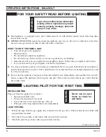
 FOR YOUR SAFETY READ BEFORE LIGHTING 

  TO TURN OFF GAS   

1.  Open lower door.
2.  Turn RS-OFF_ON rocker switch to “OFF”.
3.  Turn off all electric power to the appliance if service is to be performed.
4.  Close lower door. 

WARNING

If you do not follow these instructions 
exactly, a fire or explosion may result 
causing property damage, personal 
injury or loss of life.

WARNING

Never use an open flame 
to check for gas leak. 

Summary of Contents for SDV Series

Page 1: ...he vicinity of this or any other appliance WHAT TO DO IF YOU SMELL GAS Do not try to light any appliance Do not touch any electrical switch do not use any phone in your building Immediately call your gas supplier from a neighbor s phone Follow the gas supplier s instructions If you cannot reach your gas supplier call the fire department Installation and service must be performed by a qualified ins...

Page 2: ...ilot Ignition Wiring 32 Remote Wall Mounted Switch 32 Optional DC Remote System 32 Canopy Installation and Glass Removal 33 Brick Installation 34 Logs and Rock Wool Installation 35 Operating Instructions Millivolt 38 What To Do If You Smell Gas 38 Lighting Pilot for the First Time 38 Lighting Pilot Millivolt 39 Lighting Burner Millivolt 40 To Turn Off Gas Millivolt 40 Operating Instructions Electr...

Page 3: ...perly seated and sealed If this unit is not properly installed by a qualified service person with glass door properly seated and sealed combustion leakage can occur CARBON MONOXIDE POISONING Early signs of carbon monoxide poisoning are similar to the flu with head aches dizziness and or nausea If you have these signs the fireplace may not have been installed properly Get fresh air at once Have the...

Page 4: ...son to arrange for replacement of the unit 19 Do not operate fireplace if any log is broken 20 Do not use a blower insert heat exchanger insert or any other accessory not approved for use with this fire place 21 Do not operate the fireplace with glass door removed cracked or broken 22 For Massachusetts residents only see pages 56 and 57 IMPORTANT PLEASE READ THE FOLLOWING CAREFULLY It is normal fo...

Page 5: ...ecessed installations Hi Lo Knob PRODUCT SPECIFICATIONS CODE APPROVAL Direct Vent type appliances draw all combustion air from outside of the dwelling through the vent pipe These appliances have been tested by CSA and found to comply with the established standards for DIRECT VENT GAS FIREPLACE HEATERS in the USA and Canada as follows LISTED VENTED GAS FIREPLACE HEATER TESTED TO ANSI Z21 88 2005 CS...

Page 6: ... instructions carefully Inspect all contents for shipping damage and immediately inform your dealer if any damage is found Do not install any unit with damaged incomplete or substitute parts Check your packing list to verify that all listed parts have been received You should have the following Fireplace Firebox and Burner System Fasteners Front Floor Brick Assembly White Toggle Switch Rock Wool N...

Page 7: ...lled directly on a combustible floor or raised on a platform of an appropriate height When the firebox is installed directly on carpeting tile or other combustible material other than wood flooring the firebox shall be installed on a metal or wood panel extending the full width and depth of the enclosure Corner Installation Stud Location Inside Chase Installation Recessed Installation Figure 2 Fra...

Page 8: ...er of Pipe 233 16 33 8 403 8 5 8 5 8 1 2 1 2 341 2 5 21 2 2 A Ref to Framing C D E Ref to Wall 73 8 121 16 PRE INSTALLATION INFORMATION Figure 3 SDV500 Fireplace Dimensions FIREPLACE DIMENSIONS SDV500 SDV500 SDV600 A 4113 16 4713 16 B 323 16 383 16 C 3215 16 3815 16 D 36 42 E 41 47 F 161 8 191 8 ...

Page 9: ... and draperies due to heat from appliance Never obstruct the front opening of the fireplace Do not install in the vicinity where gasoline or other flammable liquids may be stored Vent pipe routing See Venting section found in this manual for allowable venting configurations These units can be installed in a bedroom See National Fuel Gas Code ANSI Z233 1 NFPA 54 current edition the Uniform Mechanic...

Page 10: ...ur 4 screws to attach fireplace to framing The side brackets or nail ing flanges are designed to accommodate two thickness of wall boards 1 2 or 5 8 SECURING FIREPLACE TO FLOOR OR FRAMING Figure 5 Securing Fireplace to Floor and Framing Studs Framing Framing 1 2 Nail Flange 1 2 Nail Flange Screws Screws Screws Screws Screws 1 2 Nail Flange 1 2 Nail Flange 5 8 Nail Flange 5 8 Nail Flange ...

Page 11: ...e Mantel Ceiling and Side Wall WARNING Follow these instructions carefully to ensure safe installation Failure to follow instructions exactly can create a fire hazard The appliance cannot be installed on a carpet tile or other combustible material other than wood flooring If installed on carpet or vinyl flooring the appliance shall be installed on a metal wood or noncombustible material panel exte...

Page 12: ...ns FINISHING MATERIAL NOTE Any remote wiring i e remote control wall switch and optional fan must be done prior to final finishing to avoid costly reconstruction INSTALLATION INFORMATION Only noncombustible materials i e brick tile slate steel or other materials with a UL fire rating of Zero may be used to cover the black surface of the appliance A 300 F minimum adhesive may be used to attach faci...

Page 13: ...m must NEVER be attached to a chimney serving a separate solid fuel burning appliance Each gas appliance must use a separate vent system Do not use common vent systems WARNING Horizontal sections of this vent system require a minimum of 3 clearances to combustibles at the top of the flue and 1 clearance at the sides and bottom until the flue penetrates the outside wall A minimum 1 clearance all ar...

Page 14: ... cover and gasket See Figure 9 4 Remove six 6 screws securing the flue pipe to the back of the intake box and remove the pipe and gasket See Figure 10 5 Replace flue pipe to top of firebox Ensure the gasket is in place and undamaged Secure with six 6 screws See Figure 11 6 Place the flue pipe cover and gasket removed in step 3 over the flue opening in bottom of the intake box 7 Refit the flue pipe...

Page 15: ... each floor level If an offset is needed in the attic additional pipe and elbows will be required You may use a chase with a vent termination with exposed pipe on the exterior of the house See Installing Vent System in a Chase below If pipe is enclosed in chase it is not exposed It is very important that the venting system maintain its balance between the combustion air intake and the flue gas exh...

Page 16: ...ir supply inlet to building or the combustion air inlet to any other appliance 12 305mm minimum K Clearance to a mechanical air supply inlet 6 1829mm minimum L Clearance above a paved sidewalk or paved driveway located on public property 7 2133mm minimum M Clearance under veranda porch deck or balcony See Figure 13 page 17 For Canada 12 305mm minimum N Clearance above a roof shall extend a minimum...

Page 17: ...ine the relationship between the vertical and horizontal dimensions of the vent system 1 Determine the height of the center of the horizontal vent pipe exiting through the outer wall Using this dimension on the Sidewall Vent Graph below locate the point intersecting with the slanted graph line 2 From the point of this intersection draw a vertical line to the bottom of the graph 3 Select the indica...

Page 18: ...will slide straight into matching slots on the male end of adja cent pipes and fittings Push the pipe sections together and twist one section clockwise approximately one quarter turn until the sec tions are fully locked See Figure 16 2 See venting and termination instructions for further instructions 3 Locate and cut the vent opening in the wall For combustible walls first frame in opening Combust...

Page 19: ... assembly Use wood screws provided to attach the standoff See Figure 19 5 Slide the wall thimble over the vent pipe before connecting the horizontal run to the vent cap See Figure 20 6 Carefully move the fireplace with vent assembly attached toward the wall and insert the vent pipe into the horizontal termination The pipe overlap should be a minimum of 11 4 Apply silicone to the outer pipe connect...

Page 20: ...e siding It is best to locate the fireplace in such a way that minimizes the number of offsets and horizontal vent length The horizontal vent run refers to the total length of vent pipe from the flue collar of the fireplace or the top of the transition elbow to the face of the outer wall or the mounting flange of the termination Figure 21 Maximum Three 3 90 Elbows Per Installation The maximum numb...

Page 21: ...lus B must not be greater than 17 5 2m The maximum number of 45 elbows permitted per side wall installation is two 2 These elbows can be installed in either the vertical or horizontal run For each 45 elbow installed in the horizontal run the length of the horizontal run MUST be reduced by 18 45cm This does not apply if the 45 elbows are installed on the vertical part of the vent system The maximum...

Page 22: ...x65 8 venting Ifthereducerisinstalledattherear of the unit you must immediately follow with a 90 elbow for a vertical rise before continuing with any horizontal run There is a minimum total height of 7 feet from the fireplace floor to the last section of pipe Refer to graph on page 17 1 Locate and cut the vent opening in the wall For combustible walls first frame in opening Combustible Interior Wa...

Page 23: ...base of snorkel Install drain pipe Install window well not supplied Refill hole with 12 of coarse gravel leaving a clearance of approximately 4 below snorkel See Figure 28 3 Install vent system 4 Ensure a watertight seal is made around the vent pipe coming through the wall 5 Apply high temperature sealant caulking supplied around the 5 and 8 snorkel collars 6 Slide the snorkel into the vent pipes ...

Page 24: ...n Figure 30 for vertically vented applications Up to three 3 restrictor discs may be needed for 40 installation The two 2 restrictor discs suppled will work for most installations If a third disc is needed order Part No 56D3027 You may use a reducer to 4 x65 8 in vertically vented applications NOTICE A restrictor disc must be installed on any vertical termination that is higher than 12 ...

Page 25: ... installation The maximum angular variation allowed in the system is 270 See Figure 32 The minimum height of the vent above the high est point of penetration through the roof is 1 305mm 1 2 3 4 1 2 3 4 Example Elbow 1 90 Elbow 2 45 Elbow 3 45 Elbow 4 90 Total Angular Variation 270 Figure 31 Support Straps for Horizontal Runs 40 Maximum Height 8 Minimum Height 40 Maximum Height 8 Minimum Height 10 ...

Page 26: ...ramed to 101 2 x101 2 267mm x 267mm inside dimensions as shown in Figure 34 using framing lumber the same size as the ceiling joist If the area above the ceiling is an insulated ceiling or a room nail firestop from the top side This prevents loose insulation from fall ing into the required clearance space See Figure 34 Otherwise install firestop below the framed hole The firestop should be install...

Page 27: ...nt cap meets the minimum requirements below NOTE You must increase vent height for steep roof pitches Nearby trees adjoining roof lines steep pitched roofs and other similar factors may cause poor draft or down drafting in high winds Increasing the vent height may solve this problem NOTE If the vent pipe passes through any occupied areas above the first floor including storage spaces and closets y...

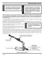
Page 28: ...ol inlet is 3 8 NPT For propane LP connections only the installer must supply an external regulator The external regulator will reduce incoming gas pressure You must reduce incoming gas pressure to between 11 and 13 inches of water If you do not reduce incoming gas pressure burner system regulator damage could occur Install external regulator with the vent pointing down as shown in Figure 37 Point...

Page 29: ...on may be made using 1 2 rigid tubing or an approved flex connector Since some municipalities have additional local codes it is always best to consult your local authorities and the current edition of the National Fuel Gas Code ANSI Z223 1 NFPA54 In Canada CAN CGA B149 1 or 2 Installation Code We recommend that you install a sediment trap drip leg in supply line as shown in Figure 38 Locate sedime...

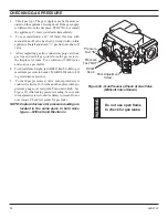
Page 30: ...and soap or a gas sniffer 4 To adjust flame height turn HI LO knob to HI to get maximum pressure to burner Turn HI LO knob to LO to get minimum pressure 5 To check gas pressures at valve turn captured screw counter clockwise 2 or 3 turns and then place tubing to pressure gauge over test point Turn unit to high See Figure 39 After taking pressure reading be sure and turn captured screw clockwise fi...

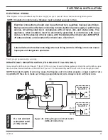
Page 31: ... ELECTRICAL WIRING Verify proper operation after servicing This fireplace will work without any electrical supply except to operate blower and electronic ignition system NOTE If installed in mobile home fireplace must be bolted securely to floor WARNING Electrical connections should only be performed by a qualified licensed electrician Main power must be off when connecting to main electrical powe...

Page 32: ... REMOTE SYSTEMS These instructions replace the section entitled Hearth Mount in the Millivolt hand held remote instructions supplied with the remote 1 Follow instructions on remote control to snap remote cover plate to remote receiver 2 Connect the wire terminal from the remote receiver This replaces the 15 wall switch connection to the switch See Figure 41 3 Use screws that came with remote contr...

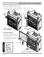
Page 33: ...into place Figure 42 Removing Top Louver Assembly Figure 43 Installing Canopy Louver Assembly Screws Canopy GLASS FRAME REMOVAL 1 Remove louver assembly from the top 2 Release three 3 clamps on bottom of fire place See Figure 44 3 Tilt glass frame out and lift glass frame up until it clears hook on top of fireplace 4 Set glass frame aside Figure 44 Removing Glass Frame CAUTION Each clamp has a qui...

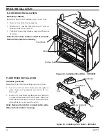
Page 34: ...ick SDV500C Firebox Tabs Slots Floor Brick Figure 46 Installing Floor Brick SDV600C FLOOR BRICK INSTALLATION SDV600C 4 PIECE Install floor brick before installing logs or rock wool 1 Locate two 2 rear floor bricks left and right in spaces between log supports and side walls See Figure 46 2 Join two 2 front bricks together as shown Rest two 2 joined front bricks on front of burner Make sure firebox...

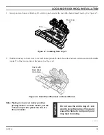
Page 35: ...entire bag of rock wool to cover the burner This could cause the flame to burn poorly and may lead to sooting 2 Distribute one layer of rock wool to cover all burner ports in the rear the surface between extrusions and in the middle center 6 of the front portion of the burner See Figure 48 Figure 48 Rock Wool Placement on Rear of Burner Note Placing rock wool on burner provides glowing embers For ...

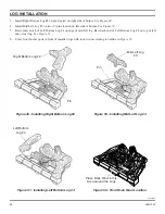
Page 36: ... Figure 50 5 Rest center notch of Left Bottom Log 4 on edge of mid left log Rest back end of Left Bottom Log 4 on top of left end or rear log See Figure 51 6 Cover front burner ports in front of installed logs with rock wool according to outline in Figure 52 Figure 51 Installing Left Bottom Log 4 Right Bottom Log 2 Pin Pin Mid Left Log 3 Left Bottom Log 4 Figure 52 Front Rock Wool Location Place R...

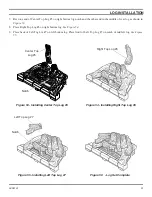
Page 37: ...e 7 Rest one end of Center Top Log 5 on right bottom log notch and the other end in the middle of rear log as shown in Figure 53 8 Place Right Top Log 6 on right bottom log See Figure 54 9 Place back of Left Tog Lot 7 on left bottom log Place front of Left Top Log 7 on notch of mid left log See Figure 55 Center Top Log 5 Right Top Log 6 Left Top Log 7 Notch Notch ...

Page 38: ... in a fire or explosion D Do not use this appliance if any part of it has been under water Immediately call a qualified service tech nician to inspect the appliance and to replace any part of the control system and any gas control that has been under water OPERATING INSTRUCTIONS MILLIVOLT FOR YOUR SAFETY READ BEFORE LIGHTING LIGHTING PILOT FOR THE FIRST TIME INITIAL LIGHTING Purge air from the sup...

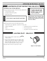
Page 39: ...gnitor as many times as needed to ignite the pilot Keep knob fully depressed for a few seconds Release and check that pilot continues to burn If the pilot does not stay lit repeat steps 1 and 2 Figure 57 Pilot Position Check for gas leaks in each of the following locations Pipe from the gas supply line connection to the gas valve Burner connections Field made joints gas shutoff valve Pilot Factory...

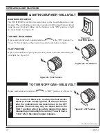
Page 40: ...on See Figure 59 It will take less than four 4 seconds for the burner to ignite PILOT POSITION Depress and turn knob to pilot position to keep burner off while maintaining the pilot light See Figure 60 Depress and turn knob clockwise to OFF position See Figure 61 TO TURN OFF GAS MILLIVOLT Figure 61 Off Position Figure 60 Pilot Position Continued on next page WARNING The control is fitted with a sa...

Page 41: ... appliance area for gas Be sure to smell next to the floor because some gas is heavier than air and will settle on the floor WHAT TO DO IF YOU SMELL GAS Turn off all gas to the appliance Open windows Do not attempt to light any appliance Do not touch any electric switch do not use any phone in your building Immediately call your gas supplier from a neighbor s phone Follow the gas supplier s instru...

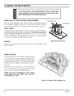
Page 42: ...R PILOT AND CONTROL COMPARTMENT Keep the control compartment logs and burner areas surrounding the logs clean by vacuuming or brushing at least twice a year Make sure the burner porting pilot air opening and burner air opening are free of obstructions at all times PILOT FLAME The flames from the pilot should be visually checked as soon as the heater is installed and periodically during normal oper...

Page 43: ...used Handle glass door with care to avoid striking or scratching it on hard objects To clean glass door follow Glass Removal procedure outlined in the Final Installation section Film deposit on the inside of the glass should be cleaned off using a nontoxic non corrosive non abrasive mild cleaning solution Simply apply an adequate amount to the glass and wipe off with a damp cloth After all mainten...

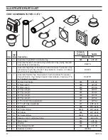
Page 44: ...ation Kit with Horizontal Termination Cap with Built In Vinyl Siding Standoff Heat Deflector Firestop 20 to 40 Flexible Pipe Adapter BHSFTK 2 1 Vertical Termination 980 4DT VC 3 6 6 Pipe Length 908 4DT 06 3 6 9 Pipe Length 907 4DT 09 3 6 12 Pipe Length 906 4DT 12 3 6 24 Pipe Length 904 4DT 24 3 6 36 Pipe Length 903 4DT 36 3 6 48 Pipe Length 902 4DT 48 4 6 11 To 14 5 8 Pipe Adjustable 911 4DT AJ 4 ...

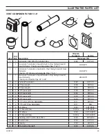
Page 45: ...nation Cap with Built In Vinyl Siding Standoff Heat Deflector Firestop and Flexible Pipe 24 to 48 BHSF8TK 2 1 Vertical Termination 1280 5DT VC 3 4 6 Pipe Length 1208 5DT 06 3 4 9 Pipe Length 1207 5DT 09 3 4 12 Pipe Length 1206 5DT 12 3 4 24 Pipe Length 1204 5DT 24 3 4 36 Pipe Length 1203 5DT 36 3 4 48 Pipe Length 1202 5DT 48 4 4 11 To 14 5 8 Pipe Adjustable 1211 5DT AJ 4 4 17 To 24 Pipe Adjustable...

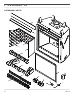
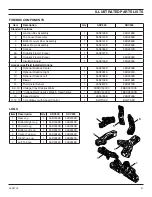
Page 46: ...46 56D2161 1 5 10 3 2 4 6A 6B 9 8 13 7 12 11 11 ILLUSTRATED PARTS LISTS FIREBOX COMPONENTS ...

Page 47: ...Center 1 56D2030K 56D2230K 9 Optional Firebrick Right 1 56D2031K 56D2031K 10 Optional Firebrick Left 1 56D2032K 56D2032K 11 Blower 2 56D2162K 56D2162K 12 Thermostat Sensor 1 26D2870K 26D2870K 8 9 10 Cottage Clay Firebrick Walls 1 FBSDV500CC FBSDV600CC 6 8 9 10 Cottage Red Firebrick Walls Hearth Brick 1 FBSDV500CR FBSDV600CR 13 Speed Control 1 26D0746K 26D0746K 11 12 13 T stat Blower with Speed Con...

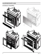
Page 48: ...48 56D2161 ILLUSTRATED PARTS LISTS ADDITIONAL ACCESSORIES 1 2 3 4 5 ...

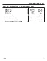
Page 49: ...er Louvers 6 6 L36BR L36PW L42BR L42PW 3 Screen Frame Black 1 SDV500SDC SDV600SDC 4 4 4 4 Cabinet Door Frame Black Cabinet Door Frame Iron Age Cabinet Doors with Screen Black Cabinet Doors with Screen Iron Age 1 1 1 1 VSDVC500CDFB VSDVC500CDFIA VSDVC500CDB VSDVC500CDIA VSDVC600CDFB VSDVC600CDFIA VSDVC600CDB VSDVC600CDIA 5 5 Arched Front with Lower Control Door Black Arched Front with Lower Control...

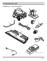
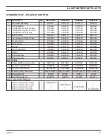
Page 50: ...50 56D2161 ILLUSTRATED PARTS LISTS 1 2 3 4 5 6 7 10 STANDING PILOT MILLIVOLT CONTROL 2T 2I 2C 9 11 12 13 14 15 16 8 ...

Page 51: ...4D0503 14D0503 14D0503 14D0503 7 Injector 1 58D0102 20H3144 56D0614 57D0680 8 Burner Assembly 1 56D2099 56D2099 56D2099 56D2099 9 Venturi 1 45D0600 45D0600 45D0600 45D0600 10 Wire Assembly 1 44D0500 44D0500 44D0500 44D0500 10 Wire Assembly 1 44D0501 44D0501 44D0501 44D0501 Accessories 11 Thermostatic Remote Control 1 RCT TRC RCT TRC RCT TRC RCT TRC 12 Remote Control On Off 1 RCM MRC RCM MRC RCM MR...

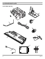
Page 52: ...52 56D2161 1 2 3 4 5 6 7 L O HI ILLUSTRATED PARTS LISTS 1 2 3 4 5 6 7 9 ELECTRONIC IGNITION 8 10 11 ...

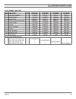
Page 53: ...69D0030 5 Rocker Switch 1 41D0048 41D0048 41D0048 41D0048 6 Injector 1 58D0102 20H3144 56D0614 57D0680 7 Burner Assembly 1 56D2099 56D2099 56D2099 56D2099 8 Venturi 1 45D0600 45D0600 45D0600 45D0600 9 Wire Assembly 1 54D2007 54D2007 54D2007 54D2007 10 Ignition Module 1 37D0325 37D0325 37D0325 37D0325 11 Transformer 1 022788 022788 022788 022788 Conversion Kit Not Shown 500 Conversion NG to LPG 500...

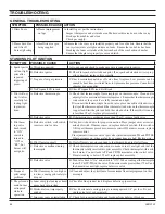
Page 54: ...TH and TP TH If burner comes on wires are faulty or connections are bad Replace wire B Pilot flame too small B If pilot flame is not close enough to the thermopile adjust pilot flame C Defective or malfunctioning thermopile C Check thermopile wire connections to make sure all are tight and that the thermopile is fully inserted into pilot assembly Check thermopile with a mil livolt meter Connect le...

Page 55: ... Check electrical connections between module and pilot operator on gas control C Check for 24VAC across PV MVPV terminals If voltage is correct replace gas control If voltage is not correct replace module NOTE If module goes into lockout reset system A Check continuity of ignition cable and ground wire B Clean flame rod C Check electrical connections between flame rod and module D Is ceramic flame...

Page 56: ...d by the Commonwealth and where the side wall exhaust vent termination is less than seven 7 feet above finished grade in the area of the venting including but not limited to decks and porches the following requirements shall be satisfied 1 INSTALLATION OF CARBON MONOXIDE DETECTORS At the time of installation of the side wall horizontal vented gas fueled equipment the installing plumber or gas fitt...

Page 57: ...e dwelling building or structure used in whole or in part for residential purposes c MANUFACTURER REQUIREMENTS GAS EQUIPMENT VENTING SYSTEM PROVIDED When the manufacturer of Product Approved side wall horizontally vented gas equipment provides a venting system design or venting system components with the equipment the instructions provided by the manufacturer for installation of the equipment and ...

Page 58: ...58 56D2161 NOTES ...

Page 59: ...56D2161 59 NOTES ...

Page 60: ...the installation instructions The Limited Lifetime Warranty will also be void if the appliance is not operated and maintained according to the operating instructions supplied with the appliance and does not extend to 1 firebox burner assembly damage by accident neglect misuse abuse alterations negligence of others including the installation thereof by unquali fied installers 2 the costs of removal...

Reviews: