Technical service manual
17
UK
(as described in the relative paragraph).
- Disconnect the connector on the search circuit board and the pick up cable on the
motherboard.
- Unscrew the three fixing screws on the beam and remove the central unit.
- Fit the new central unit. The three fixing screws must be tightened to a torque of 48 Nm.
- Replace the search circuit board complete with support.
- Reconnect the pick up and search board connectors.
- Replace the motor complete with support and adjust the wheel spin device.
- Replace the sensor, reversing the operations carried out to disconnect it.
- Calibrate the sensor as described in the operator’s manual.
- Perform a few wheel spins and check that the wheel spin device is operating correctly.
- Perform sensitivity calibration both in CAR environment (with a car wheel) and in
TRUCK environment (with a truck wheel).
ADJUSTING THE WHEEL SPIN DEVICE
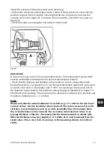
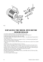
- Open the weight-holder lid, first undoing the fixing screws.
- Undo the lock-nut (D, fig. 3) which fixes the adjuster washer (A, fig. 3).
- Completely tighten the adjuster check nut (D, fig. 3). This eliminates the preload of
the spring (B, fig 3).
- Undo the screws which fix the motor support (C, fig. 3) to the beam underneath.
- Position the motor unit so that the drive roller and the pulley are about 4-5 mm apart
and the axis of the motor is parallel to that of the central unit.
- Tighten the screws which fix the motor support.
- Preload the spring (B, fig. 3), unscrewing the check nut (D, fig. 1); until the gap be-
tween the drive roller and the pulley has been reduced to 2 mm.
- Tighten the lock-nut.
- The wheel spin device has a limit stop screw which dampens the residual oscillations
of the drive unit at the end of the wheel spin phase.
Adjust the limit stop as follows:
• position the screw so that it is not touching the leaf spring;
• make sure that the drive unit is in the rest position (drive roller 2 mm from the pul-
ley);
• tighten the screw until it slightly preloads the leaf spring of the motor support;
- Perform a few trial wheel spins and check that the wheel spin device is operating cor-
rectly.
- Close the weight-holder lid again.
- If the screw (E, Fig.3) does not slide freely when activating the cylinder, turn the nut
(F, Fig.3).
Summary of Contents for MT 2450
Page 1: ...MT 2450 Code 4 131046_uk 12 2013 Technical service manual...
Page 25: ...Technical service manual 25 UK Note...
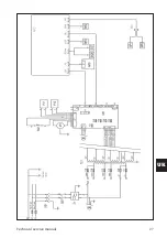
Page 27: ...Technical service manual 27 UK...
Page 28: ...28 Technical service manual...
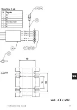
Page 29: ...Technical service manual 29 UK Cod 4 101700...
Page 30: ...30 Technical service manual...
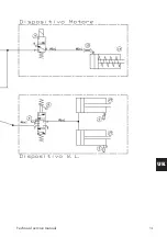
Page 31: ...Technical service manual 31 UK...
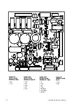
Page 32: ...32 Technical service manual...
Page 33: ...Technical service manual 33 UK Cod 457674B...
Page 34: ...34 Technical service manual...


