background image

Technical service manual 

13

UK

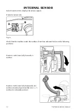
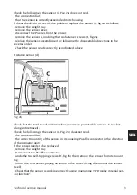
Check the following if the sensor (A, Fig. 2a) does not read:
- the connection flat;
- that the sensor is correctly assembled in its housing.
If these checks do not rectify the problem, replace the sensor (A, fig.2a) as follows:
- remove the weight tray
- remove the sensor lever;
- disconnect the Picoflex from the sensor;
- remove the sensor A, undoing the two fastener screws (B, fig.2a);
- replace the sensor, assembling it by following the disassembly directions in the 
reverse order;
- check the sensor reads correctly, as indicated above.

Distance sensor [d]

Fig.2b

Check that the total travel is 750 notches (maximum permissible error +/- 5 notches 
along entire travel);
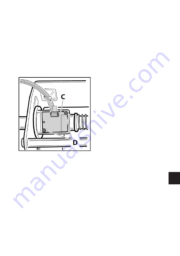
Check the following if the sensor (C, Fig. 2b) does not read:
- the connection flat;
- the correct mounting of the sensor in its housing (Picoflex connector in the direction 
of the swinging unit);
If the sensor needs to be replaced:
- remove the weight tray
- Disconnect the Picoflex connector;
- undo the two self-tapping screws (D, fig.2b) then remove the sensor from its mount-
ing;
- mount the new sensor, paying attention to the correct fixing direction of the sensor 
itself;
- Check that the sensor is working correctly using programme 98 “Display internal sen-
sor function”.

Summary of Contents for MT 2450

Page 1: ...MT 2450 Code 4 131046_uk 12 2013 Technical service manual...

Page 2: ...otice Les droits de traduction de m morisation lectronique de reproduction et d adaptation compl te ou partielle par tout type de moyen y compris microfilms et copies pho tostatiques sont r serv s Les...

Page 3: ...UNIT OF THE MBE BOARD 9 DOWNLOADING THE SOFTWARE AND FIRMWARE FROM THE INTERNET FOR CARD UPDATING 9 UPDATING THE FIRMWARE FOR THE MBE161 CARD 10 INSIDE SENSOR 12 REPLACING AND ADJUSTING THE PICK UPS...

Page 4: ...left hand display and the message Ent flashes on the right hand display to indicate that Enter must be pressed to confirm the selection made press the Enter key to confirm If the preselection is not c...

Page 5: ...he left display when programme 91 is selected When the ENTER key is pressed the diameter measured with the automatic sensor is then displayed with the precision of a tenth of an inch the message oF 5...

Page 6: ...of an encoder one notch corresponds to about 1 4 degrees To exit from the program and the Service environment press the F key The program is used to check that the values of the synchronisation calibr...

Page 7: ...fter which the shaft s current angle appears To exit from the program and the Service environment press the F key The program is used to check the efficiency of the search circuit board When the shaft...

Page 8: ...logue selection of groups EM7xxx or EM8x JEXT1 Set on EM8xxx Jumper for analogue selection of groups EM7xxx or EM8x E2PROM t4 MEMORY ZERO SETTING PROGRAMME Proceed as follows to perform the E2PROM cal...

Page 9: ...el Board description MBE161 card Processing board and interface with completely LED based display The board is controlled by a microprocessor with relative firmware The MBE161 card firmware version ca...

Page 10: ...d UPDATING THE FIRMWARE FOR THE MBE161 CARD To update the firmware the SAB16X programme is necessary If it is not already instal led on the PC to be used for the update it can be downloaded beforehand...

Page 11: ...elect the Start key to start the programming The programme starts by deleting the software version on the card to be updated displaying the following image on the status bar When the Programming box o...

Page 12: ...signals Diameter sensor di Fig 2a Check that the machine reads the number of notches indicated below in the following positions Position 1 with lever fully forwards 0 notches Position 2 with lever fu...

Page 13: ...eads correctly as indicated above Distance sensor d Fig 2b Check that the total travel is 750 notches maximum permissible error 5 notches along entire travel Check the following if the sensor C Fig 2b...

Page 14: ...e the flat cable of sensor C figure 2b ensure that the flat cable is reconnected correctly on the board see fig 2c The flat cable must be fas tened to the base leaving a sufficient length of free cabl...

Page 15: ...ioned values with a precision of a tenth of an inch on the display select OFF for rounding to the nearest inch of the diameter values read by the automatic sensor display as described in chapter 91 Th...

Page 16: ...ls E from 110 to 170 If the values displayed at the end of the wheel spin are not within the specified ranges adjust the dowels to regulate the tightness of the pick ups until the conditions are met T...

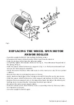
Page 17: ...r washer A fig 3 Completely tighten the adjuster check nut D fig 3 This eliminates the preload of the spring B fig 3 Undo the screws which fix the motor support C fig 3 to the beam underneath Position...

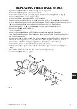
Page 18: ...ort assembly Check the state of the drive roller and reuse it on the new motor only if it is in perfect condition Remove the roller by undoing the screw on the top Apply medium thread glue to the lock...

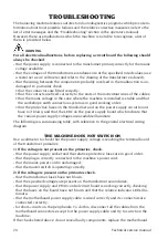
Page 19: ...pulley D fig 4 unscrewing the two fixing dowels E fig 4 Remove the brake shoes A fig 4 Fit the new shoes Apply medium thread glue to the locking dowels and replace the pulley Turn the shaft by hand an...

Page 20: ...transformer and on the power supply circuit board have not blown and that the LEDs on the power supply board which indicate that the various power supply voltages are available illuminate The followi...

Page 21: ...control cable connecting the motherboard to the power supply and con trol circuit board is connected and wired correctly that the power supply and control circuit board is operating correctly that the...

Page 22: ...this pro ceed as follows tighten the board s four fixing screws placed close to its edges lightly engage the two nuts close to the keys until they turn with friction press all the keys on the panel t...

Page 23: ...the position of the imbalances correctly In this case the following must be checked that the photodiodes of the search circuit board are not dirty that the mechanical setting of the fork in relation...

Page 24: ...correctly and its connectors are connected correctly that the power supply and PEAC control circuit board is operating correctly that the motherboard power supply cable is wired correctly and its con...

Page 25: ...Technical service manual 25 UK Note...

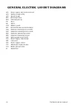
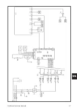
Page 26: ...up FU Fuse M1 Motor QS1 Master switch RP1 Internal distance potentiometer SQ6 Distance resetting micro switch SQ7 Diameter resetting micro switch BR2 Diameter measuring sensor BR3 Distance measuring...

Page 27: ...Technical service manual 27 UK...

Page 28: ...28 Technical service manual...

Page 29: ...Technical service manual 29 UK Cod 4 101700...

Page 30: ...30 Technical service manual...

Page 31: ...Technical service manual 31 UK...

Page 32: ...32 Technical service manual...

Page 33: ...Technical service manual 33 UK Cod 457674B...

Page 34: ...34 Technical service manual...

Page 35: ...Technical service manual 35 UK Cod 4 104447A...

Page 36: ...MONDOLFO FERRO S p a Viale dell industria 20 61037 MONDOLFO PU Italy info mondolfoferro it www mondolfoferro it CE COMIM Cod 4 131046 12 2013...

Reviews: