background image

 MONARK MEDICAL TREADMILL


15

14  

MONARK MEDICAL TREADMILL

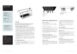
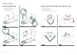
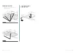
OPEN ELECTRONIC BOX

1. 
1. 

Remove cover, see section “Remove cover”

2. 

Remove two M4 screws, see fig: 1

3. 

Tilt cover as shown in image, see fig: 2 and fig: 3

4. 

Remove electronic box cover

FIGURE: 2

FIGURE: 3

FIGURE 1

FIGURE 1

FIGURE 2

FIGURE 3

FIGURE: 4

2 x M4

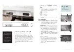
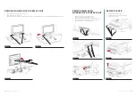
REMOVE INCLINE MOTOR

1. 

Remove cover, see section “Remove cover”

2. 

Remove upper M12 screw and lock nut, see fig: 1

3. 

Remove lower M12 screw and lock nut, see fig: 2

4. 

Slide out incline motor, see fig: 3

1 x M12, screw, lock nut

1xM12
screw
lock nut

Summary of Contents for MEDICAL TREADMILL

Page 1: ...MANUAL MONARK MEDICAL TREADMILL ENGLISH...

Page 2: ...novo Display Unit 12 Remove Monark novo Control Unit 13 Remove Cover 13 Open Electronic Box 14 Remove Incline Motor 19 IMPORTANT Before using your new treadmill please read the manual carefully and sa...

Page 3: ...ront connections Now the treadmill is ready for use Press the green on off button 7 on the control panel and the band starts at a speed of 0 1 km h To increase the speed press up on speed button 11 to...

Page 4: ...have been paired the heart rate monitor Bluetooth ID and the current heart rate is displayed at Pulse You can choose to actively lock the heart rate monitor by pressing Lock Then the treadmill is only...

Page 5: ...lips or moves to one side it needs to be adjusted This is done by adjusting the two M10 screws at the rear roller see fig Adjusting the running belt Checking the tension of the motor belt Check the te...

Page 6: ...emove 16 M8 screws see fig 3 5 Lift up and remove handle bars see fig 4 REMOVE PANEL WITH MONARK NOVO DISPLAY UNIT 1 Remove two M4 screws see fig 1 2 Open protective cover as shown in fig 2 3 Disconne...

Page 7: ...M4 REMOVE PANEL WITH MONARK NOVO CONTROL UNIT 1 Remove cover see section Remove cover 2 Disconnect all cables from Control Unit 3 Remove two M4 screws and nuts from outside see fig 1 4 Remove two M4...

Page 8: ...own in image see fig 2 and fig 3 4 Remove electronic box cover FIGURE 2 FIGURE 3 FIGURE 1 FIGURE 1 FIGURE 2 FIGURE 3 FIGURE 4 2 x M4 REMOVE INCLINE MOTOR 1 Remove cover see section Remove cover 2 Remo...

Page 9: ...own in fig 3 6 Slide out and remove back roller see fig 4 7 Loosen screws for motor belt tensio ner see fig 5 8 Remove belt from motor belt wheel see fig 6 9 Remove M10 screw from front roller see fig...

Page 10: ...EDICAL TREADMILL MONARK MEDICAL TREADMILL 19 REMOVE CASTOR 1 Remove two M12 screws and locknuts see fig 1 2 Remove castors see fig 2 ADJUSTABLE REAR SUPPORT FEET Castors 2 x M12 screws locknuts FIGURE...

Page 11: ...the market The unique calibration method which provides incomparable control and accuracy makes it easy for clinicians to safely apply the prescribed workload in rehabilitation programs and stress tes...

Reviews: