VIDEO
DC IN
AUDIO
ANT
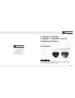
2.4 GHz Wireless Colour Camera
and Receiver
Please read these operating instructions carefully
prior to operating the unit and keep them for later ref-
erence.
1
Applications
The set DVT-410SET consists of a wireless camera, a
receiver and two power supply units. It serves to cre-
ate a wireless video surveillance system. For this pur-
pose, a colour monitor is additionally required. The
picture transmission is digital.
The camera is accommodated in a weatherproof
housing (IP 66) and is therefore also suitable for out-
door applications. In case the illumination is insuffi-
cient, the camera switches to black-and-white opera-
tion and the 27 infrared LEDs illuminate a range of up
to 10 m approx.
The transmission range depends to a large extent
on local conditions. It may be up to 80 m if there are no
obstacles between camera and receiver. However, the
range is reduced in buildings to approx. 30 m depend-
ing on the condition of the walls and ceilings.
1.1 Conformity and approval
Herewith, MONACOR INTERNATIONAL declare that
the set of units DVT-410SET is in accordance with
the basic requirements and the other relevant regula-
tions of the directive 1999 / 5 / EC. The declaration of
conformity is available on request from MONACOR
INTERNATIONAL.
The set operates in the 2.4 GHz range and is gen-
erally approved for operation in EU and EFTA coun-
tries and is licence-free.
2
Safety Notes
The units (camera, receiver and power supply units)
correspond to all required directives of the EU and are
therefore marked with
.
G
The power supply units and the receiver are suitable
for indoor use only.
G
Protect the units against excessive temperatures
(admissible ambient temperature range -10 °C to
+50 °C), and additionally protect the power supply
units and the receiver against dripping water and
splash water and high air humidity.
G
Do not set the receiver or the camera into operation,
and immediately disconnect the corresponding
power supply unit from the socket if
1. there is visible damage to one of the units,
2. a defect might have occurred after a drop or sim-
ilar accident,
WARNING
The power supply units are supplied
with hazardous mains voltage. Leave
servicing of these units to skilled per-
sonnel only. Inexpert handling or modi-
fication may cause an electric shock
hazard.
3. malfunctions occur.
The units must in any case be repaired by skilled
personnel.
G
For cleaning only use a dry, soft cloth, never use
chemicals or water. The camera may also be
cleaned with a cloth slightly damp.
G
No guarantee claims for the units and no liability for
any resulting personal damage or material damage
will be accepted if the units are used for other pur-
poses than originally intended, if they are not cor-
rectly connected or operated, or not repaired in an
expert way.
3
Operation
Prior to the first setting into operation the camera must
be assigned to one of the four transmission channels.
This is easy as long as the camera is not yet mounted.
Therefore, first perform steps 1 to 7 and then mount
the camera.
1) If required, tightly screw the support (13) of the
receiver at the desired place and place the receiver
into the support. Place the reception antenna (7) in
a vertical position.
2) Connect the audio output (10) and the video output
(11) via the supplied cable to the corresponding
inputs of a monitor.
3) Connect one of the two supplied power supply units
to the jack DC IN (12) and to a socket (230 V~ /
50 Hz).
4) Switch on the monitor. As long as no camera signal
is received, a signal can be heard from the monitor
speaker. The screen displays:
If no stable picture appears or if NTSC is shown
instead of PAL, press the small recessed button (9)
with a thin object so that PAL is shown.
5) Screw the transmitting antenna (1) to the jack (2) of
the camera and place it in a vertical position. Con-
nect the second power supply unit to the inline jack
(5) and to a socket (230 V~ / 50 Hz).
6) Use the button
(8) at the receiver to select the
receiving channel which is to be assigned to the
camera (indication CAM 1 – 4 on the monitor). Then
keep the button
pressed for approx. 3 seconds
until the following message is shown on the screen:
CAUTION When setting up the camera, never look
directly into the lit IR LEDs from a close range. The
infrared light may cause eye irritation. However,
the infrared radiation is far below the emission limit
and rated risk-free according to EN 62471.
If the units are to be put out of operation
definitively, take them to a local recycling plant
for a disposal which is not harmful to the
environment.
NO SIGNAL
CAM 1 PAL
7) Press the pushbutton for momentary action (6) of
the camera within 30 seconds. (The number at the
bottom of the screen message shows the remain-
ing time in seconds.) Thus, the camera is assigned
to the selected channel and the camera picture
appears on the monitor.
8) Now mount the camera at the desired place. For
this purpose, screw the supplied camera support
into the threaded jack (3) on the upper side or lower
side. Connect the power supply unit and align the
camera to the surveillance range.
9) The receiver may receive the signals of up to four
cameras if further cameras are used. For this pur-
pose repeat the steps 5 to 8 for each camera. Use
the button
(8) to switch over the individual cam-
era pictures and to a 4-fold picture with all camera
pictures.
4
Specifications
General information
Transmitting frequency: . . . 2.4 GHz
Video system: . . . . . . . . . . PAL / CCIR
Ambient temperature: . . . . -10 °C to +50 °C
Wireless camera
Transmitting power: . . . . . . < 10 mW
Image sensor: . . . . . . . . . . 6.35 mm (
1
/
4
″)
CMOS chip
Number of pixels: . . . . . . . hor. 640 × vert. 480
Resolution: . . . . . . . . . . . . 380 lines
Lens: . . . . . . . . . . . . . . . . . 1 : 2/6.0 mm,
viewing angle 50°
Power supply: . . . . . . . . . . 5 V , 850 mA max.
via supplied PSU con-
nected to (230 V~ / 50 Hz)
Receiver
Video output: . . . . . . . . . . . 1 Vss/75 Ω
Power supply: . . . . . . . . . . 5 V , 350 mA max.
via supplied PSU con-
nected to (230 V~ / 50 Hz)
Subject to technical modification.
Important! The pushbutton for momentary action
(6), the inline jack (5) for the power supply unit and
the cable distributor (4) are not weatherproof. In
case of outside connection they must be protected
accordingly.
Please Press
Pair Key
on Sensor side
30
CAM 1 PAL
DVT-410SET
Order No. 18.8730
®
1
2
3
4
5
6
MONACOR INTERNATIONAL GmbH & Co. KG • Zum Falsch 36 • 28307 Bremen • Germany
Copyright
©
by MONACOR INTERNATIONAL. All rights reserved.
A-1308.99.02.10.2013
®
GB
3
7
8
9
10
11
12
13