


Parameterisation manual
Manual No.:
MWF-PA102
Microwave level measurement
MWF
Index
0
Date
08.08.18
Adaption of parameters with the MWF2-KIT
Page 4 of 9
2.
Parameterisation of the MWF electronic
2.1 General information
1.
The MWF has been completely parametrised corresponding to your requirements ex works.
If the adaption of parameters is required, you should change only these parameters.
2.
You find a sheet with all factory settings for the measuring parameters in the appendix of the
supplied operation manual of the MWF.
3.
All necessary changes can be executed in the register
Basic configuration
.
4.
In order to change the value of a parameter, please insert the requested value in the orange colored
field in the column
variable
.
With a click on
SEND
this value will be sent to the MWF electronic.
After a short time
„ok“ is shown in the field
status.
The new value has been stored in the MWF electronic. (The previous value has been overwritten)
5.
In order to secure your changes please store the Excel-file on the connected PC.
With it the changed parameters can be checked again at any time or the Excel-file can be sent to
MOLLET for support.
6.
During the process of parameterisation you can use the display on the
MWF-HART-D2
modem for
monitoring the current output (4
– 20 mA). This is done by pressing the red button for switching on
the display. After that you can read the actual measured value (filling level).
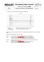
2.2 Parameterisation
Line 2 to 5
Setting of measuring range [M]
This is where the lower and upper measuring limits are parameterised. The values correspond to the
length at the probe in mm, measured from the reference point [R].
1.
Insert in
line 2
the value for the lower measuring limit
[uMG] 4 mA
.
2.
Insert in
line 3
the value for the upper measuring limit
[oMG] 20 mA
.
Line 6 and 7
No input
These values are for factory setting only. Please don´t do any changes!
Line 8 to 13
Setting of switching output
This is where the switching output is parameterised.
The switch-on and switch-off points of the switching output can be set at different positions within the
measuring range [M] (switching hysteresis) by setting different values for lower and upper switch points.
By using the same value for lower and upper switch points the least switching hysteresis is 3mm of the
probe length.
1.
Insert in
line 8
the function of the switching output. The factory setting
NC
can be change to
NO
by
setting the value
„1“.
2.
Insert in
line 10
the value of the lower point of the switching output
[uSA]
and in
line 12
the value of
the upper point of the switching output
[oSA]
.
The values correspond to the length at the probe in mm, measured from the reference point
[R]
.