


Parameterisation manual
Manual No.:
MWF-PA102
Microwave level measurement
MWF
Index
0
Date
08.08.18
Adaption of parameters with the MWF2-KIT
Page 3 of 9
1.1 Connection to the MWF electronic
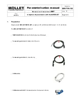
There are two possibilities to connect the
MWF-HART-D2
modem with the MWF electronic:
1.1.1 Connection direct to the device:
1.
Separate the MWF electronic temporary from the power supply.
2.
Open the lid of the MWF housing.
3.
Loosen the wire from the terminal
„
+
“ of the 4-20 mA signal output.
4.
Connect the blank end of the
measuring wire A
to the empty
„
+
“ terminal of the 4-20 mA signal
output.
5.
Connect the loosened wire with crocodile clip of the
measuring wire B
.
6.
Put both plugs of the
measuring wires A
and
B
into the sockets
A
and
B
at the front end of the
MWF-HART-D2
modem.
7.
Connect the MWF electronic to the power supply again and wait approx. 10 seconds until the
electronic is ready for operation.
1.1.2 Connection to measuring value display or control device:
1.
Separate the MWF electronic temporary from the power supply.
2.
Loosen the wire from the signal input
„
+
“ of the measuring value display or control device.
3.
Connect the blank end of the
measuring wire A
to the empty „
+
“ terminal of the measuring value
display or control device.
4.
Connect the loosened wire with the crocodile clip of the
measuring wire B
.
5.
Put both plugs of the
measuring wires A
and
B
into the sockets
A
and
B
at the front end of the
MWF-HART-D2
modem.
6.
Connect the MWF electronic to the power supply again and wait approx. 10 seconds until the
electronic is ready for operation.
1.2 Laptop/PC connection and installation
1.
Copy the
MWF Parameterisation-Tool
from the USB stick to the Laptop/PC.
2.
Start the program and open register
HOME
.
3.
Connect the
MWF-HART-D2
modem and the Laptop/PC with the
USB cable.
4.
Open the Device Manager in the Windows Control Panel of the Laptop/PC. In the list with
connections a HART modem is indicated.
5.
Enter the number of the COM Port, that is mentioned behind the name of the HART modem (e.g. 4)
into the spreadsheet of the
MWF Parameterisation-Tool
and confirm the input with ENTER.
6.
Change into the register
Basic configuration
and click in
line 1
on
CONNECT
. After a few seconds
the serial number of the connected device is shown in field
variable
and in field
status
is shown
„ok“.
That means the connection between Laptop/PC and MWF device is correctly established.
If the serial number is not indicated and in field
status
is not
„ok“ shown, please check the
establishment of the connections and the determining and input of the COM Port number.
7.
Close the Device Manager.