AT-1992 Hand Crimp Tool
Doc No:ATS-640070100
Release Date: 10-03-02
UNCONTROLLED COPY
Page 11 of 15
Revision: J
Revision Date: 08-08-13
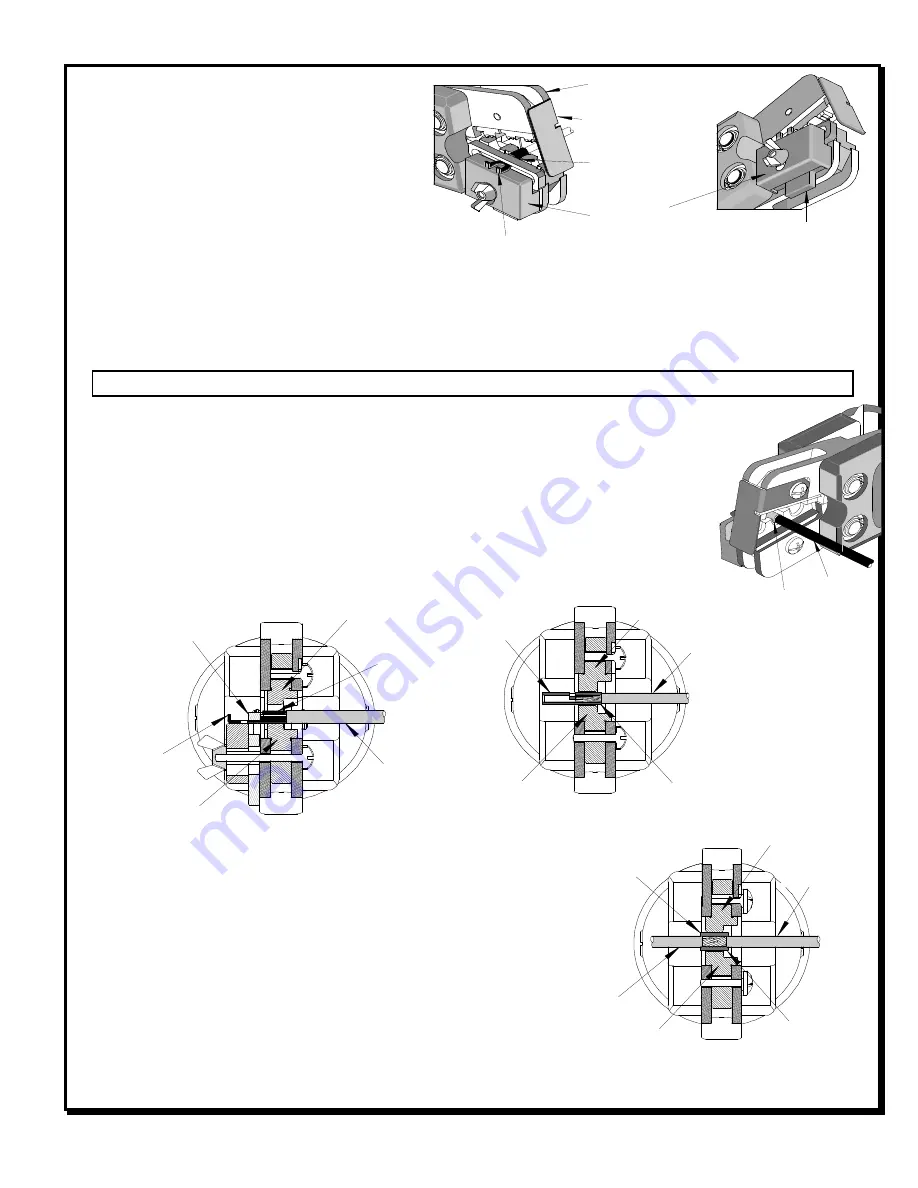
Figure 1
JAWS OPEN
SAFETY
SHIELD
FRONT EDGE
OF BARREL
LOCATOR
PUSH UP TO
LOAD TERMINAL
TERMINAL
TERMINAL
BARREL
TERMINAL
LOCATOR
WIRE
CONDUCTOR
ANVIL
Figure 3
CONDUCTOR
PUNCH
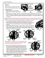
Operation
Refer to the instruction manual for the 19279-
0001 (AT-200) for mounting this crimp tool head.
Crimping Terminals
1.
Adjust the locator up or down until the
terminal being run sits flat and straight in the
tool.
2.
Insert the wire into the terminal. Push up on the locator blade and insert the terminal and wire into the proper
nest with the barrel up and against the locator bar. Release the locator blade to hold the terminal in position. See
Figure 1. Locator may be raised or lowered so terminal sits flat and straight in tool. The locator must be removed
to run splices.
Caution:
Never operate this tool without the supplied safety shield in place. Never place fingers in the tool nests.
3.
Push on the wire to assure it is fully seated in the terminal. See Figure 2 and 3. The
wires end should butt against the wire stop position of the locator. Cycle the tool.
4.
Lift the locator blade or wire stop and remove the crimped terminal. Inspect for proper
crimp location. Locator is adjustable up and down to keep terminals straight after
crimping.
5.
When crimping butt splices, the locator must be removed. Insert the wire into the butt
splice. Position the splice and the wire in proper coded nest with conductor crimp on the
conductor barrel of the splice The splice should be approximately centered inside the
tooling nests. See Figure 4. Cycle the tool.
Note
: Whenever crimping without the locator, make sure the seam
of the terminal is oriented up or down in the tool if using unbrazed
product, as this will provide higher pull force values.
6.
When crimping parallel splices, the locator must be removed.
Insert the 1
st
wire into one end of splice then insert the 2
nd
wire
into the opposite end of the parallel splice. This procedure will
crimp both wires at the same time. Make sure the wires are fully
seated into the parallel splice. Position the splice and the wires
in proper coded nest with conductor crimp on the conductor
barrel of the splice The splice should be approximately centered
inside the tooling nests. See Figure 5. Cycle the tool.
WIRE
TERMINAL
Figure 2
BUTT
SPLICE
VISUALLY
CENTER SPLICE
BARREL
CONDUCTOR
PUNCH
CONDUCTOR
ANVIL
Figure 4
WIRE
CONDUCTOR
ANVIL
Figure 5
VISUALLY
CENTER SPLICE
BARREL
PARALLEL
SPLICE
CONDUCTOR
PUNCH
2
ND
WIRE
1
ST
WIRE


