background image

Hand Crimp Tool for Ditto Wing Genderless Interconnects Terminals 

Doc No: ATS-638278600 

Release Date: 09-29-15 

UNCONTROLLED COPY


Page 2 of 8 

Revision: B 

Revision Date: 08-20-19 

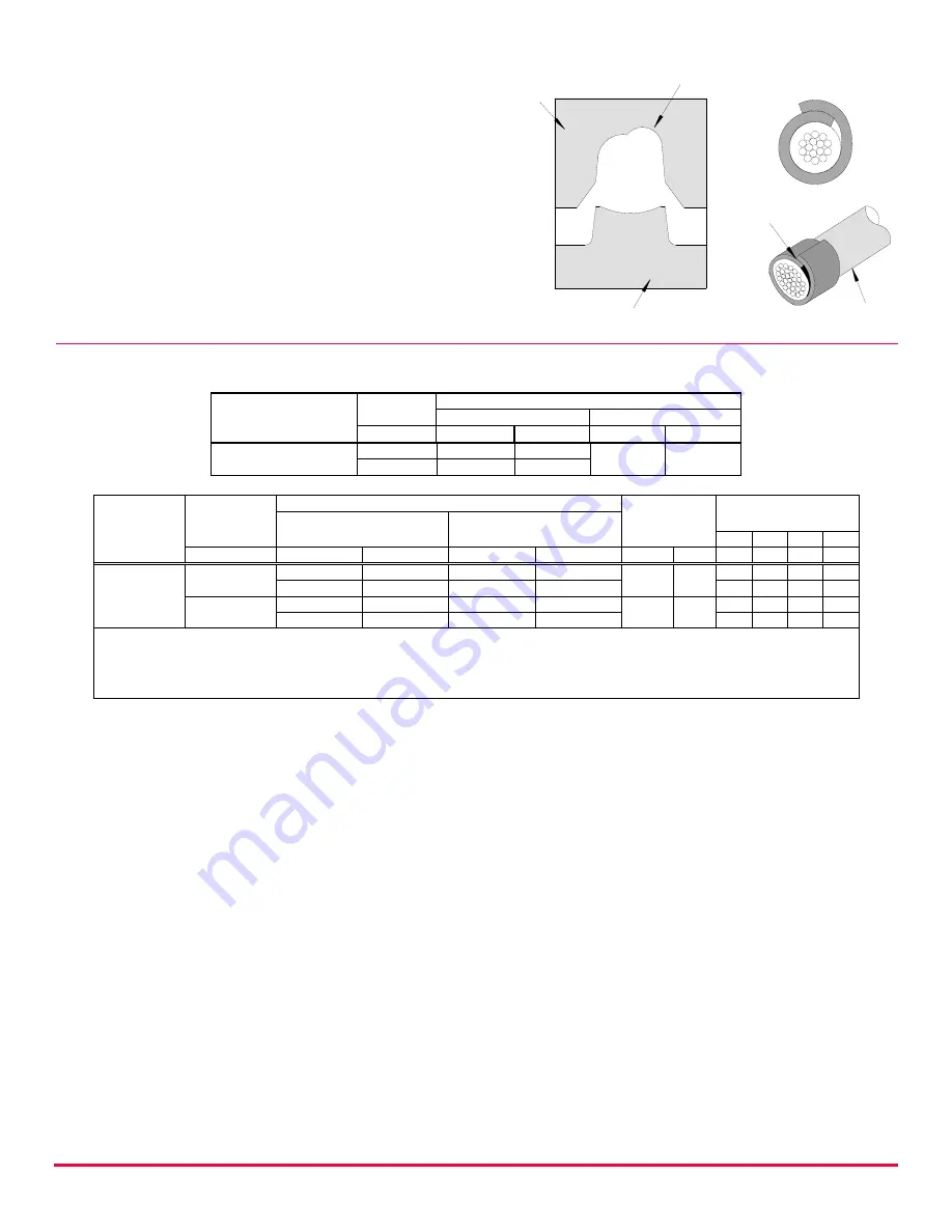
Insulation Crimp Note


Due to the terminal’s insulation grip design 
and insulation diameter range, this tool uses 
overlap form geometry in the insulation 
punch. This produces an overlap insulation 
crimp (A-620 compliant). Although the 
insulation punch profile may appear lopsided, 
this is a normal condition for this tool. See 
figure to the right. Some tools with multiple 
crimp pockets may not have the overlap 
profile on all pockets. 


CONDITIONS 

 
After crimping, the conductor profiles should measure the following: 


Terminal Series No 

Wire Size 

Conductor Crimp 

Height 

Width 

AWG 

mm 

In. 

mm 

In. 

150197 

150200 

24 

0.95–1.05  .037-.041 

1.40-1.50  .055-.059 

26 

0.95–1.00  .037-.039 


Terminal 

Series No 

Wire Size 

Insulation Crimp Maximum 

Pull Force 

Minimum 

Profile 

Height (Ref.) 

Width (Ref.) 

AWG 

mm 

In. 

mm 

In. 

Lb. 

26  24  24  26 

150197 

150200 

24 

1.75-1.85 

.069-.073 

1.75-1.85 

.069-.073 

26.7 

6.0 


1.55-1.65 

.061-.065 

1.55-1.65 

.061-.065 


26 

1.75-1.85 

.069-.073 

1.75-1.85 

.069-.073 

17.8 

4.0 


1.50-1.60 

.059-.063 

1.40-1.50 

.055-.059 


To achieve IPC/WHMA-A-620 Class 2 crimps, the following overall wire insulation diameter ranges are recommended: 

Profile A:

 1.30-1.40mm (.051-.055”)    

Profile C:

 1.10-1.20mm (.043-.047”) 

Profile B:

 1.35-1.55mm (.053-.061”)    

Profile D:

 0.80-1.00mm (.031-.039”) 


Tool Qualification Notes 


1.  Pull force should be measured with no influence from the insulation crimp. 
2.  The above specifications are guidelines to an optimum crimp. 


Note 


A crimp height chart is provided with this document as Reference Only. Due to the wide range of 
wires, strands, insulation diameters, and durometers available, actual crimp height measurements 
may very slightly. An occasional destructive pull force test should be performed to check hand tool 
crimp. Pull force value must exceed the minimum pull force specifications listed. 


OVERLAP 

INSULATION 

CRIMP 

OVERLAP FORM GEOMETRY 

ANVIL 

PUNCH 

WIRE 

Summary of Contents for 63827-8600

Page 1: ...ol Order No 63816 0270 110 V or 63816 0280 220 V with the use of the 63816 0800 Crimp Head Many different tool kits can be used with a single Battery Powered Crimp Tool This tool is IPC WHMA A 620 Class 2 compliant see page 2 This tool is RoHS compliant however RoHS compliance is not required SCOPE Products Ditto Wing Genderless Interconnects Terminal 24 26 AWG Terminal Series No Terminal Order No...

Page 2: ...imum Profile Height Ref Width Ref A B C D AWG mm In mm In N Lb 26 24 24 26 150197 150200 24 1 75 1 85 069 073 1 75 1 85 069 073 26 7 6 0 X 1 55 1 65 061 065 1 55 1 65 061 065 X 26 1 75 1 85 069 073 1 75 1 85 069 073 17 8 4 0 X 1 50 1 60 059 063 1 40 1 50 055 059 X To achieve IPC WHMA A 620 Class 2 crimps the following overall wire insulation diameter ranges are recommended Profile A 1 30 1 40mm 05...

Page 3: ...nal listed from the preceding charts and install it in the proper locator See chart above and see Locator Replacement on page 4 2 Make sure the center of the locator is in the down position With the locator attached push the locator button on the back of the hand tool to bring the locator forward through the tooling See Figure 2 3 While holding in the locator button load the terminal into the prop...

Page 4: ...ist on the last page of this document for the proper locator order number Follow the steps below to replace the locator 1 Open the hand crimp tool 2 Squeeze gently on the lower area shown in Figure 7A with your thumb and index finger The lower tabs of the locator should disengage from the hand tool 3 Lift and pull away from the hand tool The top locator hooks should slip out of the top slots easil...

Page 5: ...ator of the tool be made aware of and responsible for the following maintenance steps 1 Remove dust moisture and other contaminants with a clean brush or a soft lint free cloth 2 Do not use any abrasive materials that could damage the tool 3 Make certain all pins pivot points and bearing surfaces are protected with a thin coat of high quality machine oil See Figure 10 Do not oil excessively The to...

Page 6: ...ockwise CW 3 Release the link to lock the setting wheel in place 4 Check the crimp specifications or conduct a pull test after tool handle preload force is adjusted Warranty This tool is for electrical terminal crimping purposes only This tool is made of the best quality materials All vital components are long life tested All tools are warranted to be free of manufacturing defects for a period of ...

Page 7: ...nly To re certify crimp a terminal to a wire that has been stripped 12 7mm 500 long so that there is no crimping of the insulation Pull the terminal and wire at a rate no faster than 25mm 1 00 per minute See the Molex website for the Quality Crimp Handbook for more information on pull testing If the tool does not meet minimum pull force values handle preload should be increased and the pull test s...

Page 8: ...3 1 3 PARTS LIST Item Number Order Number Description Quantity REF 63827 8600 Hand Crimp Tool Figure 13 1 63827 8675 Locator Assembly Red 1 2 63810 0104 Spring Return 1 3 63810 0105 Spring Ratchet 1 Molex is a registered trademark of Molex LLC in the United States of America and may be registered in other countries all other trademarks listed herein belong to their respective owners ...

Reviews: