Hand Crimp Tool for Board-In Crimp Terminals
Doc No: ATS-6382713HM
Release Date: 07-02-13
UNCONTROLLED COPY
Page 2 of 5
Revision: A
Revision Date: 07-02-13
CRIMP SPECIFICATION
Terminal Series No.
Bell mouth
Cut-off Tab Maximum Conductor Brush Maximum
mm
In.
mm
In.
mm
In.
171892
0.20-0.50 .008-.020
0.30
.012
0.45
.018
Terminal
Series No.
Bend up Bend down Twist Roll
Punch Width (Ref)
Contact Gap
(Center to Center)
Seam
Seam shall not be open and
no wire allowed out of
the crimping area
Conductor Insulation
Degree
Degree
mm
In.
mm
In
.
mm
In
.
171892
5
5
5
10
2.30 .090 2.30 .090 2.30-2.80 .090-.110
After crimping, the crimp profiles should measure the following:
Terminal Series No.
Wire Size
Conductor
Insulation
Pull Force
Minimum
Crimp Height
Crimp Width (Ref)
Crimp Height
AWG
mm
2
mm
In.
mm
In.
mm
In.
N
Lb.
171892
16
1.30
1.48-1.52
.058-.060
2.45
.096
2.45
.096
133.5
30.0
Notes:
1.
This tool should only be used for the terminals and wire gauges specified on this sheet.
2.
Pull Force should be measured with no influence from the insulation crimp.
3.
The above specifications are guidelines to an optimum crimp.
4.
Molex does not repair hand tools (see
Warranty
on page 3). The replacement parts listed are the only parts
available for repair. If the handles or crimp tooling is damaged or worn, a new tool must be purchased.
5.
Pull force should be used as the final criteria for an acceptable crimp.
Refer to Molex Quality Crimping Handbook 63800-0029 for additional
information on crimping and crimp testing.
6.
Molex does not certify crimp hand tools.
OPERATION
Open the tool by squeezing the handles together, at the end of the closing stroke, the ratchet mechanism will
release the handles, and the hand tool will spring open.
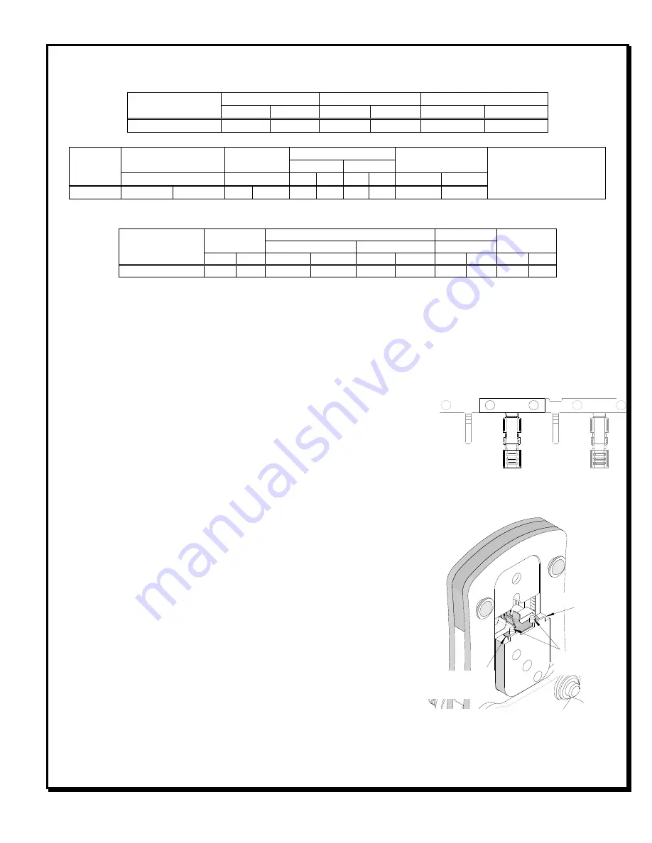
Preparing Terminals for Crimping
The terminals must be cut from the reel as shown. See Figure 1. The
carrier strip holes are used to assist in loading the terminal in position
over the crimp anvils. The carrier strip will help maintain terminal
position during crimping and can be broken off after the crimp is
complete.
Crimping Terminals
1.
Load the terminal with carrier strip onto the crimp anvils. Make sure
the carrier strip pilot holes fit over the positioning pins.
2.
Place the properly stripped wire into the open terminal barrel. Push
the wire into the tool until the end of the wire contacts the wire stop,
making sure that all wire strands are inside of the conductor barrel.
See Figures 2 and 3.
3.
While holding the wire with one hand, slowly squeeze the tool handles together to close the tool jaws until the
ratchet mechanism releases. At this point the handles can be released and will spring open.
Figure 1
LOCATOR
Figure 2
TERMINAL
CARRIER STRIP
POSITIONING
PINS