background image

Tool Kit for 250 Slip-in Receptacle Terminals 

Doc No: ATS-6382575HM  Release Date: 05-17-13 

UNCONTROLLED COPY


Page 3 of 8 

Revision:A 

Revision Date: 05-17-13 
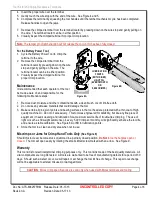
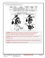
Figure 4 

WIRE IN TERMINAL 

JAWS 

PARTIALLY 

CLOSED 

WIRE AGAINST 

WIRE STOP 

HANDLE 

OPEN 

LOCATOR 

CLOSED 

Figure 3 

TERMINAL 

PUSH HERE TO 

OPEN WIRE STOP 


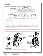
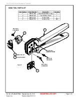
Anvils and Punches Installation


1.


Insert the Anvils into the bottom slots of the nest.  Install the M4 x 10 long BHCS and tighten in place. 

2.


Insert the Punches into the top slots of the nest.  Install the M4 x 18 long BHCS and tighten in place.  See 
Figure 1. 


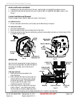
Locator Installation and Removal 

Follow the steps below to install or replace the locator.  See Figure 2. 
 

To install the locator


1.


Position the locator with the hole over the brass pivot shaft and snap it into place. 


To remove the locator 

1.


Open the crimp hand tool. 

2.


Swing the existing locator open and away from the hand tool. 

3.


Firmly press down on the brass pivot shaft with your thumb, while pulling the locator up.  Slip the locator off the 
top of the brass pivot shaft. 


OPERATION 

 
Open the tool by squeezing the handles together, at 
the end of the closing stroke, the ratchet mechanism 
will release the handles, and the hand tool will 
spring open. 
 

Crimping Terminals 

1.


Select the desired terminal listed in the 
preceding charts. 

2.


Some terminals with large insulation grips may 
interfere with the crimp tooling when swinging 
the locator into position.  This terminal must 
then be loaded into the locator in the 
closed/crimp position.  See Figure 3. 

3.


Press down on the wire stop on the locator as 
shown in Figure1.  Insert the proper terminal 
into the proper nest opening.  Make sure when 
choosing the nest opening, it will correspond with the A, B or C profile on the hand tool. 
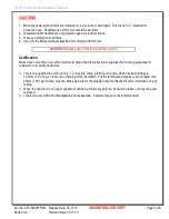
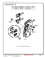
Figure 5 

WIRE 

INSULATION 

PUNCH 

CONDUCTOR ANVIL 

LOCATOR 

INSULATION 

ANVIL 

WIRES AGAINST 

LOCATOR STOP 

CONDUCTOR 

PUNCH 

TERMINAL 

Summary of Contents for 63825-7500

Page 1: ... Crimp Head which is installed into the 63816 0200 110 V or the 63816 0250 220 V Battery Powered Tool Many different Tool kits can be used with a single Battery Powered Tool This tool is IPC WHMA A 620 Class 2 and RoHS compliant SCOPE Products 250 Slip on Receptacle Terminals for 10 14 AWG Wire Terminal Series No Terminal Order No Wire Size Insulation Diameter Strip Length IPC WHMA A620 1 Terminal...

Page 2: ... mm2 mm In mm In N Lbs 35725 10 5 25 5 10 5 30 201 209 4 85 5 15 191 203 343 77 1 12 3 30 4 80 4 95 189 195 4 85 5 15 191 203 290 65 2 14 2 00 4 50 4 65 177 183 4 85 5 15 191 203 190 42 7 Tool Qualification Notes 1 Pull Force should be measured with no influence from the insulation crimp 2 The above specifications are guidelines to an optimum crimp Note A crimp height chart is provided with this m...

Page 3: ...ing the existing locator open and away from the hand tool 3 Firmly press down on the brass pivot shaft with your thumb while pulling the locator up Slip the locator off the top of the brass pivot shaft OPERATION Open the tool by squeezing the handles together at the end of the closing stroke the ratchet mechanism will release the handles and the hand tool will spring open Crimping Terminals 1 Sele...

Page 4: ...e any abrasive materials that could damage the tool 3 Make certain all pins pivot points and bearing surfaces in the tool head are protected with a thin coat of high quality machine oil Do not oil excessively This tool was engineered for durability but like any fine piece of equipment it needs cleaning and lubrication for a maximum service life of trouble free crimping The use of light oil such as...

Page 5: ...his tool should be avoided Certification Molex does not certify or re certify commercial grade hand tools but rather supplies the following guidelines for customers to re certify hand tools This tool is qualified to pull force only To re certify crimp a terminal to a wire which has been stripped 12 7mm 1 2 long so there is no crimping of the insulation Pull the terminal and wire at a rate no faste...

Page 6: ...lications for the Tool Kit Hand Crimp Tool Battery Powered Tool Figure 7 Figure 8 WARNING NEVER operate service install tool kits or adjust the Power Crimp Head without proper instruction and without first reading and understanding the instructions in the proper Manual or Specification Sheet See Chart above for the correct Manual or Specification Sheet WARNING NEVER install tooling or service this...

Page 7: ... Date 05 17 13 RATCHET RELEASE SCREW Figure 9 M4 X 8mm LONG BHCS 2 1 3 M4 X 18mm LONG BHCS M4 X 10mm LONG BHCS 2 4 WITH TOOL KIT LOCATOR ONLY HAND TOOL PARTS LIST Item Number Order Number Description Quantity 1 63810 1000 Hand Crimp Frame Long 1 2 63825 7570 Tool Kit with Locator 1 3 63811 4773 Locator Base 1 4 63825 7575 Locator only REF ...

Page 8: ...of 8 Revision A Revision Date 05 17 13 Figure 10 1 2 2 M4 by 8 Long BHCS M4 by 18 Long BHCS M4 by 10 Long BHCS 1 POWER HEAD PARTS LIST Item Order No Engineering No Description Quantity 1 63816 0300 63816 0300 Power Crimp Head 1 2 63825 7570 63825 7570 Tool Kit with Locator 1 Visit our Web site at http www molex com ...

Reviews: