Chapter 4: Maintenance
5040237 B
25
Test Input Signal Functionality
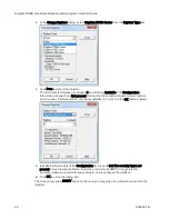
To test analog inputs signals are working with either AxoScope software or Clampex software:
1. Click
Lab Bench (or click Configure > Lab Bench) and select the Output Signals tab.
For each of the Digitizer Channels (for example, Analog OUT #0), select a matching Signal
(for example, OUT 0), and configure that signal with unity scaling (for example, Scale factor
(V/V): 1).
2. Click
Edit Protocol (or click Acquire > Edit Protocol) and then, on the Inputs tab, for
each of the Analog IN Channels, select the matching signal (for example, IN 0) from its list.
3. Connect a BNC cable from the analog outputs to the analog inputs to be tested.
4. Click
Record (or click Acquire > Record) to acquire data. For each analog output
signal, in the software, use the Real Time Controls panel to change voltage levels. Either
use the spinners or type a value and then press
ENTER
.
5. Click
Last Recording (or click File > Last Recording) to open the data file. Test the
input signal levels using the cursors in the window. To display a subset of the signals, right
‐
click on the data display area, select Properties, and go to the Show/Hide tab.

