background image

Digidata 1550B Low-Noise Data Acquisition System User Start Guide

24

5040237 B

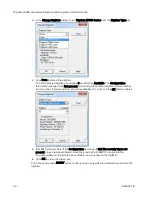
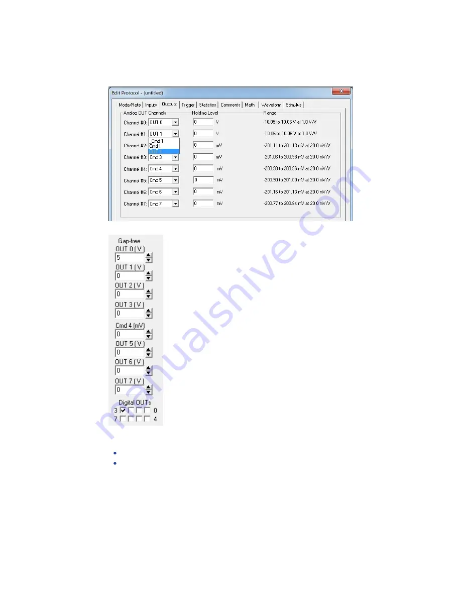
2. Set up a protocol through the Acquire > New Protocol menu command, and then on the

Mode/Rate tab, select the Gap

free mode. On the Outputs tab, for each of the Analog

OUT Channels, select the matching signal (for example, OUT 1) from its list.

3. Attach the digitizer outputs to an oscilloscope or 10-bit digital volt meter (DVM).

4. For each output signal, use the Real Time Controls panel in the software to change voltage

levels.

For analog outputs, either use the spinners, or type a value and press

ENTER

.

For digital outputs, click on the box corresponding to the digital bit to be tested. Verify
the output signal levels on the oscilloscope or DVM.

Summary of Contents for Digidata 1550B

Page 1: ...5040237 B January 2021 Digidata 1550B Low Noise Data Acquisition System Plus HumSilencer Adaptive Noise Cancellation System User Guide...

Page 2: ...y right and or license to use or permit others to use such manufacturers and or their product names as trademarks Each product is shipped with documentation stating specifications and other technicali...

Page 3: ...is used in a manner not specified by Molecular Devices the protection provided by the equipment might be impaired Symbols on Instrument Labels Each safety label found on the instrument contains an al...

Page 4: ...European Union You must not discard this electrical or electronic product or its components in domestic household waste or in the municipal waste collection system For products under the requirement o...

Page 5: ...igitizer 12 Configuring Software for Digidata 1550B Digitizer Use 13 Chapter 3 Interface Description 15 Front Panel 15 Rear Panel 19 Chapter 4 Maintenance 21 Functionality Tests 21 Grounding and Minim...

Page 6: ...50B Low Noise Data Acquisition System User Start Guide 6 5040237 B Digital Outputs 37 Telegraph Inputs 38 HumSilencer Adaptive Noise Cancellation Module 38 AC Power 38 Appendix A Electromagnetic Compa...

Page 7: ...gh Analog Input Channels 0 or Analog Input Channels 0 2 4 and 6 to eliminate 50 Hz or 60 Hz line frequency noise and associated high frequency harmonics The Digidata 1550B digitizer communicates with...

Page 8: ...t of every line power cycle is reported to the high speed logic section of the processor Using this timing signal as an input to mark the beginning and end of the power line cycle the digitization cir...

Page 9: ...rage at 1 50 amplitude This transient situation is not an issue if the peak to peak broadband noise associated with the signal is greater than about 1 25 of the amplitude of a step or spike in the sig...

Page 10: ...Digidata 1550B Low Noise Data Acquisition System User Start Guide 10 5040237 B...

Page 11: ...are version 11 only support Digidata 1440A Series digitizers and newer digitizers The new software and drivers install without removing previously installed software and drivers allowing you to contin...

Page 12: ...60221 into any USB port on the computer connected to the digitizer Depending on your software license you might receive two dongles one for data acquisition and one for data analysis The black Clampex...

Page 13: ...pment that can be damaged by such voltages during the startup period This configuration procedure applies to AxoScope software version 11 2 and Clampex software version 11 2 Demo configuration is acti...

Page 14: ...umber firmware version HumSilencer channel availability 0 1 or 4 and the OK button is enabled 5 Click OK to exit the dialog Updating the digitizer information can take up to one minute after which the...

Page 15: ...eight 16 bit single ended analog input channels The BNC shields for the Analog Inputs are connected to the Analog ground All of these channels can be used simultaneously without any reduction in thro...

Page 16: ...izer analog inputs It is not a filter and does not have a filtering effect on acquired signals nor does it cause waveform distortion such as frequency change amplitude attenuation phase shift or DC vo...

Page 17: ...bled and learning the line frequency noise Figure 3 3 Figure 3 3 The HumSilencer system Real Time Controls panel items in active learning mode but not actively canceling noise The Real Time Controls p...

Page 18: ...f the learned real time noise patterns HumSilencer Start and HumSilencer Stop comment tags are displayed in the Clampex software or AxoScope software data file For more detailed usage procedures refer...

Page 19: ...s Computer controlled amplifiers such as MultiClamp 700A B Microelectrode Amplifier and Axoclamp 900A Computer Controlled Microelectrode Amplifier use software telegraph signals instead of such hard w...

Page 20: ...Digidata 1550B Low Noise Data Acquisition System User Start Guide 20 5040237 B...

Page 21: ...e only by Molecular Devices qualified personnel When service is required contact Molecular Devices Technical Support Functionality Tests Run functionality tests to verify digitizer signals The functio...

Page 22: ...present to reporting the selected digitizer model number serial number firmware version channel availability 0 1 or 4 and the OK button enables 5 pCLAMP software Only If the Configuration field repor...

Page 23: ...us controllers tree 4 Find an entry for a USB 2 0 or USB 3 0 controller Test Output Signal Functionality To test analog and digital outputs signals are working with either AxoScope software or Clampex...

Page 24: ...elect the matching signal for example OUT 1 from its list 3 Attach the digitizer outputs to an oscilloscope or 10 bit digital volt meter DVM 4 For each output signal use the Real Time Controls panel i...

Page 25: ...and then on the Inputs tab for each of the Analog IN Channels select the matching signal for example IN 0 from its list 3 Connect a BNC cable from the analog outputs to the analog inputs to be tested...

Page 26: ...k box is selected 2 Click Edit Protocol or click Acquire Edit Protocol and then on the Inputs tab Select the Analog IN Channel 0 HumSilencer check box or if your instrument uses four ANC inputs select...

Page 27: ...inate the source of the alternating magnetic field from a cheap transformer or an electric motor such as found in a nearby fan or refrigerator Try to rearrange the two BNC cables to determine if their...

Page 28: ...the fuse If you need replacement fuses contact Molecular Devices Technical Support The Digidata 1550B digitizer uses a pair of fuses located in a fuse carrier under the AC input port For Digidata 155...

Page 29: ...37 B 29 7 Reconnect the power cord to the AC input port 8 Switch on the power from the front of the instrument Note If the instrument still does not power on after changing the fuses contact Molecular...

Page 30: ...Digidata 1550B Low Noise Data Acquisition System User Start Guide 30 5040237 B...

Page 31: ...nstruments and test the digitizer and computer combination by itself 4 Swap the unit with a known good unit to help determine whether the problem is with the digitizer or the computer Problems From Th...

Page 32: ...If noise is added to the signal on the analog input make sure that all cables are routed away from switching power supplies power cords monitors or any other major sources of noise Check for proper g...

Page 33: ...In Configure Program Options select Disable screen saver during data acquisition Obtaining Support Molecular Devices is a leading worldwide manufacturer and distributor of analytical instrumentation s...

Page 34: ...r Start Guide 34 5040237 B Clampex software users 1 Connect Analog Out 0 to Analog In 0 2 From Acquire New Protocol run an Episodic stimulation mode protocol with a default waveform specified 3 Click...

Page 35: ...Dimensions H x W x D 109 mm x 483 mm x 363 mm Mains Power Input 100 240 VAC 50 60 Hz Max 50 W Mains Voltage Fluctuations Not to exceed 10 of nominal supply voltage Equipment Class 1 Pollution Degree 2...

Page 36: ...Analog Inputs Specifications 1 Depending on the model Analog Input Channels 0 2 4 and 6 are configurable with the HumSilencer system Analog Outputs Item Description Number of channels 8 Resolution 16...

Page 37: ...igital Outputs Specifications A DB 25 pin female connector is provided on the rear panel with the following pin assignments as listed in Table 6 6 Pin Number Digital Output 1 0 2 2 3 4 4 6 5 N C 6 Ana...

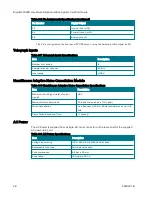
Page 38: ...lencer Adaptive Noise Cancellation Module Item Description Maximum Input Signal total of noise signal 10 V Maximum Noise Amplitude 20 V peak to peak on a 0 V signal Noise Cancellation Line frequency 5...

Page 39: ...C Notice This equipment has been tested and found to comply with the limits for a Class A digital device pursuant to part 18 of the FCC Rules These limits are designed to provide reasonable protection...

Page 40: ...ecular Devices LLC or their respective owners Specifications subject to change without notice Patents www moleculardevices com patents FOR RESEARCH USE ONLY NOT FOR USE IN DIAGNOSTIC PROCEDURES 2021 M...

Reviews: