MOGlabs FSC100 Manual Download Page 28

24

Chapter 3. Operation

Ideally the spectrum analyser would be used with an independent
frequency discriminator that is insensitive to laser power fluctua-
tions [11]. Good results can be achieved by monitoring the in-loop
error signal but an out-of-loop measurement is preferable, such as
measuring the cavity transmission in a PDH application. To ana-
lyse the error signal, connect the spectrum analyser to one of the

MONITOR

outputs set to “

FAST ERR

”.

High-bandwidth locking typically involves first achieving a stable
lock using only the fast servo, and then using the slow servo to
improve the long-term lock stability. The slow servo is required
to compensate for thermal drift and acoustic perturbations, which
would result in a mode-hop if compensated with current alone. In
contrast, simple locking techniques such as saturated absorption
spectroscopy are typically achieved using the slow servo, with the
fast servo compensating higher-frequency fluctuations only. It may
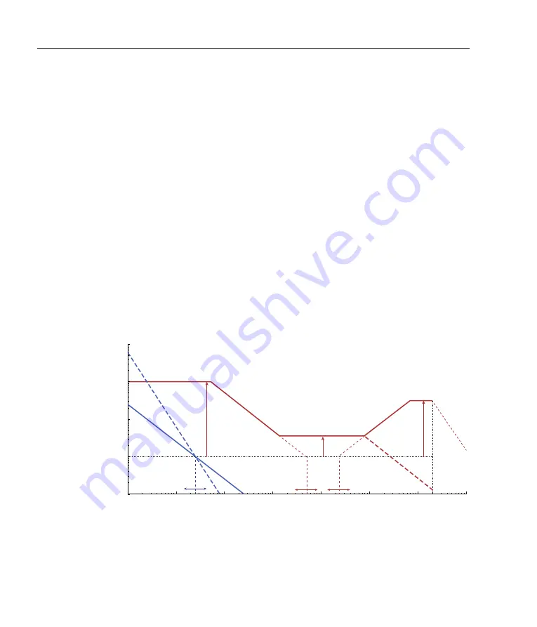
be beneficial to consult the Bode plot (figure 3.3) when interpreting
the error signal spectrum.

G

ain (dB)

20

0

40

60

–20

10

2

10

1

10

3

10

4

10

5

10

6

10

7

Fourier frequency  [Hz]

Inte

grato

r

Double in

teg

rat

or

Proportional

High fr

eq

. cut

off

Diff

eren

tia

tor

Inte

grato

r

10

8

FAST LF GAIN (limit)

FAST

GAIN

DIFF GAIN (limit)

FAST INT

FAST DIFF

SL

OW INT

Filt

er

Figure 3.3:

Conceptual Bode plot showing action of the fast (red) and slow

(blue) controllers. The corner frequencies and gain limits are adjusted with
the front-panel knobs as labelled.

Summary of Contents for FSC100

Page 1: ...Fast servo controller FSC100 Version 0 1 2 Rev 2 4 hardware ...

Page 2: ...uential damages in connections with or arising out of the performance or use of any of its products The foregoing limitation of liability shall be equally applicable to any service provided by MOGLabs Copyright Copyright c MOG Laboratories Pty Ltd MOGLabs 2017 2019 No part of this publication may be reproduced stored in a retrieval system or transmitted in any form or by any means electronic mecha...

Page 3: ...ntrols 11 2 2 Rear panel controls and connections 15 2 3 Internal DIP switches 17 3 Operation 19 3 1 Laser and controller configuration 20 3 2 Achieving an initial lock 22 3 3 Optimisation 23 A Specifications 27 B 115 230 V conversion 29 B 1 Fuse 29 B 2 120 240 V conversion 29 References 34 i ...

Page 4: ...ii Contents ...

Page 5: ...e frequency of the laser is measured with a frequency discrimi nator which generates an error signal that is proportional to the difference between the instantaneous laser frequency and the de sired or setpoint frequency Common discriminators include optical cavities and Pound Drever Hall PDH 4 or Ha nsch Couillaud 5 detection offset locking 6 or many variations of atomic absorption spectroscopy 7...

Page 6: ...laser diode or an acousto optic or electro optic modulator such that the laser frequency returns to the setpoint Actuators have complica ted response functions with finite phase lags frequency dependent gain and resonances A compensator should optimise the control response to reduce the error to the minimum possible The operation of feedback servos is usually described in terms of the Fourier freq...

Page 7: ...the sum of three components derived from the one input error signal The proportional feedback P attempts to promptly compensate for disturbances whereas integrator feedback I provides high gain for offsets and slow drifts and differential feedback D adds extra gain for sudden changes When using a single integrator the gain decreases at 20 dB per decade of Fourier frequency change indicating a stro...

Page 8: ...s The slow controller is either a single or double integrator with adjustable corner frequency The fast controller is PID with adjustable corner frequencies and gain limits at the low and high frequencies Optionally the differentiator can be disabled and replaced with a low pass filter Alternatively applications that do not require a differentiator may benefit from low pass filtering of the fast s...

Page 9: ...rator 2 Slow error SLOW SERVO Gain SLOW GAIN 0v 1 2 SLOW OUT LF sweep SLOW INT SLOW INT B IN 0v CHB VREF A IN ERR OFFSET FAST SIGN SLOW SIGN INPUT DC block 0v 0v INPUT B A MODULATION SWEEP MOD IN 0v 0v Bias 3 FAST OUT TRIG BIAS 0v LF sweep 0v SPAN 0v 0v Fixed offset 5 OFFSET SWEEP IN RATE Ramp Slope 6 INT EXT External gain 1 FAST SERVO FAST GAIN P I D NESTED 0v GAIN IN 0v Mod 4 LOCK IN FAST FAST L...

Page 10: ... lock point Some applications may benefit from small adjustments to the DC level to adjust this lock point which can be achieved with the 10 turn knob ERR OFFSET for up to 0 1 V shift provided the INPUT selector is set to offset mode Larger offsets can be achieved with the REF trimpot B IN 0v CHB VREF A IN ERR OFFSET FAST SIGN SLOW SIGN INPUT FE SE SLOW ERR Fast error Slow error FAST ERR DC block ...

Page 11: ...W SERVO Gain SLOW GAIN 0v 1 2 SLOW OUT LF sweep LF SLOW Integrators SLOW INT SLOW INT Figure 1 6 Schematic of slow feedback I I2 servo Hexagons are monitored signals available via the front panel selector switches The purpose of the slow servo is to compensate for long term drifts and acoustic perturbations that are undesirable for the fast servo to respond to For example if the fast servo is modu...

Page 12: ...abled When set to SCAN P the proportional feedback is applied which allows for determination of the fast servo sign and gain while the laser frequency is still scanning simplifying the locking and tuning procedure see 3 2 In LOCK mode the scan is halted and full PID controller is engaged External gain 1 Fast error FAST SERVO FAST GAIN P I D NESTED 0v Slow control Fast control GAIN IN LOCK IN FAST ...

Page 13: ...the sweep and activates stabilisation Fast control MODULATION SWEEP MOD IN 0v 0v Bias 3 FAST OUT TRIG HF FAST BS BIAS RA RAMP BIAS 0v LF sweep 0v SPAN 0v 0v Fixed offset 5 OFFSET SWEEP IN RATE Ramp Slope 6 INT EXT LOCK IN FAST LOCK IN SLOW 0v Mod 4 0v FAST LOCK SLOW LOCK Figure 1 8 Sweep external modulation and feedforward current bias The ramp can also be added to the fast output by enabling DIP3...

Page 14: ...10 Chapter 1 Introduction ...

Page 15: ... SLOW CHA CHB FAST ERR SLOW ERR RAMP BIAS FAST SLOW MON1 MON2 Fast Servo Controller CHB PD 0 REF 100k 200k OFF 10M 1M 750k 500k 5M 2 5M 50k 25k 100k 250k OFF 10k 20k 50k 500k 1M 2M 100k 200k OFF 25 50 75 500 750 1k 100 250 CHA CHB FAST ERR SLOW ERR RAMP BIAS FAST SLOW STATUS 0 6 18 24 12 2 1 1 Configuration INPUT Selects error signal coupling mode see figure 1 5 AC Fast error signal is AC coupled ...

Page 16: ... provided by some laser controllers such as the MOGLabs DLC and should only be used when not provided elsewhere SPAN Adjusts the ramp height and thus the extent of the frequency sweep FREQ OFFSET Adjusts the DC offset on the slow output effectively providing a static shift of the laser frequency 2 1 3 Loop variables The gain of each proportional integrator and differentiator stage can be adjusted ...

Page 17: ... 4 Lock controls GAIN LIMIT Low frequency gain limit on the fast servo in dB MAX represents the maximum available gain ERROR OFFSET DC offset applied to the error signals when INPUT mode is set to Useful for precise tuning of the locking point or compensating for drift in the error signal The adjacent trimpot is for adjusting the error offset of the slow servo relative to the fast servo and may be...

Page 18: ...lect which of the specified signals is routed through to the rear panel MONITOR 1 and MONITOR 2 outputs The TRIG output is a TTL compatible output that switches from low to high at the centre of the sweep The table below defines the signals CHA Channel A input CHB Channel B input FAST ERR Error signal used by the fast servo SLOW ERR Error signal used by the slow servo RAMP Ramp as applied to SLOW ...

Page 19: ...ly voltage if needed A IN B IN Error signal inputs for channels A and B typically photodetectors High impedance nominal range 2 5 V Channel B is unused unless the CHB switch on the front panel is set to PD POWER A B Low noise DC power for photodetectors 12 V 125 mA supplied through an M8 connector TE Connectivity part number 2 2172067 2 Digikey A121939 ND 3 way male To be used with standard M8 cab...

Page 20: ... driver or other slow actuator FAST OUT Fast control signal output 2 5 V Normally connected to diode in jection current acousto or electro optic modulator or other fast actuator MONITOR 1 2 Selected signal output for monitoring TRIG Low to high TTL output at sweep centre LOCK IN TTL scan lock control 3 5 mm stereo connector left right pins 2 3 for slow fast lock low ground is active enable lock Fr...

Page 21: ...he front panel FAST GAIN knob DIP 2 Slow servo is a single OFF or double ON integrator Should be OFF if using nested slow and fast servo operation mode DIP 3 Generate a bias current in proportion to the slow servo output to prevent mode hops Only enable if not already provided by the laser controller Should be OFF when the FSC is used in combination with a MOGLabs DLC DIP 4 Enables external modula...

Page 22: ...18 Chapter 2 Connections and controls ...

Page 23: ...us TRIG CH1 Serial TRIG FAST OUT SLOW OUT MOD IN POWER B POWER A MONITOR 1 MONITOR 2 SWEEP IN GAIN IN B IN A IN LOCK IN Laser EOM Cavity PBS LPF PD Piezo Current Oscilloscope AC CH2 Figure 3 1 Simplified schematic for PDH cavity locking using the FSC An electro optic modulator EOM generates sidebands which interact with the cavity generating reflections that are measured on the photodetector PD De...

Page 24: ...ve the required behaviour as explained below 3 1 1 Headboard configuration MOGLabs lasers include an internal headboard that interfaces the components with the controller A headboard that includes fast cur rent modulation via an SMA connector is required for operation with the FSC The headboard should be connected directly to the FSC FAST OUT The B1240 headboard is strongly recommended for maximum...

Page 25: ...n the DLC to maximum fully clockwise Set FREQUENCY on the DLC to zero using the LCD display to set Frequency Ensure that SWEEP on the FSC is INT Set FREQ OFFSET to mid range and SPAN to full on the FSC and observe the laser scan If the scan is in the wrong direction invert DIP4 of the FSC or DIP11 of the DLC It is important that the SPAN knob of the DLC is not adjusted once set as above as it will...

Page 26: ...ob until the DC level shown is zero3 Reduce the FAST GAIN to zero Set FAST to SCAN P set SLOW to SCAN and locate the reso nance using the sweep controls Increase FAST GAIN until the error signal is seen to stretch out as shown in figure 3 2 If this is not observed invert the FAST SIGN switch and try again Set FAST DIFF to OFF and GAIN LIMIT to 30 Reduce FAST INT to 100 kHz Set FAST mode to LOCK an...

Page 27: ...ed trimpot Adjust SLOW GAIN and SLOW INT for improved lock stability Some applications may benefit by increasing FAST DIFF to im prove loop response 3 3 Optimisation The purpose of the servo is to lock the laser to the zero crossing of the error signal which ideally would be identically zero when loc ked Noise in the error signal is therefore a measure of lock quality Spectrum analysis of the erro...

Page 28: ...te for thermal drift and acoustic perturbations which would result in a mode hop if compensated with current alone In contrast simple locking techniques such as saturated absorption spectroscopy are typically achieved using the slow servo with the fast servo compensating higher frequency fluctuations only It may be beneficial to consult the Bode plot figure 3 3 when interpreting the error signal s...

Page 29: ...o both the laser controller and any electronics involved in generating the error signal One procedure for optimising the fast servo is to set FAST DIFF to OFF and adjust FAST GAIN FAST INT and GAIN LIMIT to reduce the noise level as far as possible Then optimise the FAST DIFF and DIFF GAIN to reduce the high frequency noise components as observed on a spectrum analyser In some applications the err...

Page 30: ... will reduce the sensitivity to acoustic perturbations and prolong the lifetime of the lock Similarly activating the double integrator DIP2 may improve sta bility by ensuring that the overall gain of the slow servo system is higher than the fast servo at these lower frequencies However this may cause the slow servo to overreact to low frequency perturba tions and the double integrator is only reco...

Page 31: ...ndwidth 3 dB 35 MHz Input A IN B IN SMA 1 MΩ 2 5 V SWEEP IN SMA 1 MΩ 0 to 2 5 V GAIN IN SMA 1 MΩ 2 5 V MOD IN SMA 1 MΩ 2 5 V LOCK IN 3 5 mm female audio connector TTL Analogue inputs are over voltage protected up to 10 V TTL inputs take 1 0 V as low 2 0 V as high LOCK IN inputs are 0 5 V to 7 V active low drawing 1 µA 27 ...

Page 32: ...R 1 2 SMA 50 Ω BW 20 MHz TRIG SMA 0 to 5 V POWER A B M8 female connector 12 V 125 mA All outputs are limited to 5 V 50 Ω outputs 20 mA max 20 mW 13 dBm Mechanical power IEC input 110 to 130V at 60Hz or 220 to 260V at 50Hz Fuse 5x20mm anti surge ceramic 250 V 2 5 A Dimensions W H D 250 79 292 mm Weight 2 kg Power usage 10 W ...

Page 33: ...n switch on the rear of the unit Fig B 1 Figure B 1 Fuse catridge showing fuse placement for operation at 230 V B 2 120 240 V conversion The controller can be powered from AC at 50 to 60 Hz 110 to 120 V 100 V in Japan or 220 to 240 V To convert between 115 V and 230 V the fuse cartridge should be removed and re inserted such that the correct voltage shows through the cover window 29 ...

Page 34: ...rt a screwdriver into the recess at the left of the cartridge do not try to extract using a screwdriver at the sides of the fuseholder see figures WRONG CORRECT Figure B 3 To extract the fuse cartridge insert a screwdriver into a recess at the left of the cartridge When changing the voltage the fuse and a bridging clip must be swapped from one side to the other so that the bridging clip is always ...

Page 35: ...20 240 V conversion 31 Figure B 4 230 V bridge left and fuse right Swap the bridge and fuse when changing voltage so that the fuse remains uppermost when inserted Figure B 5 115 V bridge left and fuse right ...

Page 36: ...32 Appendix B 115 230 V conversion ...

Page 37: ... stabilization using an optical resonator Appl Phys B 31 97 105 1983 1 5 T W Ha nsch and B Couillaud Laser frequency stabilization by polarization spectroscopy of a reflecting reference cavity Optics communications 35 3 441 444 1980 1 6 M Zhu and J L Hall Stabilization of optical phase frequency of a laser system application to a commercial dye laser with an external stabilizer J Opt Soc Am B 10 8...

Page 38: ... induced transparency Appl Phys Lett 90 171120 2007 1 10 W Demtro der Laser Spectroscopy Basic Concepts and Instru mentation Springer Berlin 2e edition 1996 1 11 L D Turner K P Weber C J Hawthorn and R E Schol ten Frequency noise characterization of narrow linewith diode lasers Opt Communic 201 391 2002 24 34 ...

Page 39: ......

Page 40: ...aboratories Pty Ltd 49 University St Carlton VIC 3053 Australia Tel 61 3 9939 0677 info moglabs com c 2017 2019 Product specifications and descriptions in this do cument are subject to change without notice ...

Reviews: