


7.7 Counters
51
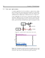
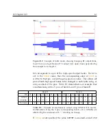
Figure 7.5:
Example of pulse generation using the
CHx-OFF
input. Red is
TTL
signal; blue is the
RF
signal.
7.7
Counters
Fast digital counters can be accessed for each digital input pin.
XRF
devices can use these counters in advanced table mode (
§
9.4);
ARF
devices can only use them manually in scripts.
To use a counter,
the associated pin must be in
READ
mode and the counter function
activated. The maximum edge-detection rate on the high-speed bus
is 50 MHz, and level-detection (
HIGH
and
LOW
modes) accumulates
125 counts per microsecond.
The
syntax
to
control
counters
is
EXTIO,COUNTER,ch,pin,command
,
where
command
is one of the following:
READ, V[ALUE]
Return the counter value as a 32-bit number
RESET, C[LEAR]
Reset the counter value to zero
E[NABLE]
Activate counter and begin accumulating count
D[ISABLE]
Deactivate counter but hold count value
Summary of Contents for ARF021
Page 1: ...Agile RF Synthesizer AOM driver ARF021 ARF421 XRF021 XRF421 Version 1 5 0 Rev 6 ...
Page 4: ...ii ...
Page 10: ...viii Contents ...
Page 26: ...16 Chapter 3 Communications ...
Page 44: ...34 Chapter 5 External modulation ...
Page 50: ...40 Chapter 6 PID stabilisation ...
Page 64: ...54 Chapter 7 Digital I O ...
Page 100: ...90 Chapter 9 Advanced table mode XRF ...
Page 128: ...118 Appendix C Command language ...
Page 133: ......


