


01/08 AWB2190-1430GB
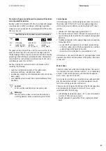
Setting the functions with DIP
switches/jumpers
79
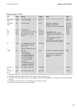
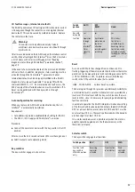
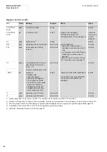
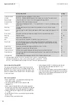
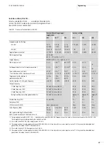
Table 11: Indication of diagnostic status
Set plug monitoring as part of Ready message
The motor plug monitoring message can also be assigned to Ready
message DI0 (
section “I/O assignment” on page 69).
This is recommended if
• the motor plug is used as isolating switch in combination with
lock shackle SET-M-LOCK (
• motors without temperature sensor winding are used and T1/T2
in the motor’s terminal board ae bridged (
a
figure 76 on page
73).
If maintenance work is performed under these conditions with
disconnected and locked motor plug, a Not Ready signal makes
more sense than a fault message.
To activate this operating mode, close the left hook jumper
(
a
table 12 on page 80).
In this opeating mode, a high-resistance connection between pins
5 and 8 of the motor plug (thermistor tripping or no motor plug)
the following effects:
• The motor switches off (as in the normal operating mode).
• No group error message is applied to DI1.
• LED Motor does not indicate a group error message.
• No Ready signal is applied to DI0, even if the key-switch is set
to AUTO.
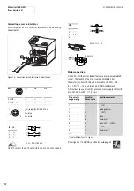
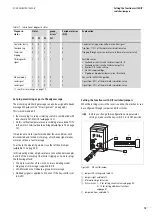
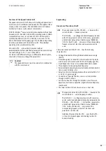
Setting the functions with DIP switches/jumpers
When the locking screw in the cover is undone, the electronics can
be configured through jumpers and DIP switches.
Diagnosic-
status
Status
group
errors
1
Peripheral error
(FID)
Explanation
P1
P2
P3
DI1
Contactor faulty
0
0
1
1
1
Contactor in On position without actuation signal
Overload trip
0
1
0
1
0
Trip from 110 % of thermal motor simulation value
Thermistor
tripping
0
1
1
1
0
Tripping through excessive resistance in thermistor sensor circuit
NO diagnostic
signal
1
1
1
1
0
Possible causes:
• Overload or short circuit of external inputs I3, I4
• Overload or short circuit of external output O3
• Incorrect DIP switch setting
• No 24 V supply voltage
• Tripping on drop below lower current threshold
Manual mode
1
0
0
0
0
Key-switch in MANUAL position
Load signal
1
0
1
0
0
Signal from 90 % of thermal motor simulation value
Load signal
1
1
0
0
0
Signal from 70 % of thermal motor simulation value
1) see I/O error message on page 75
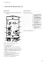
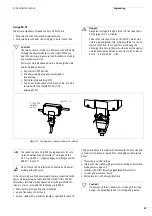
h
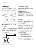
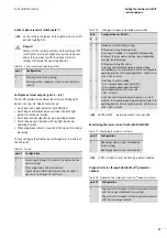
Before you change the configuration and parameter
settings, make sure the key-switch is in its OFF position.
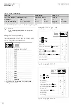
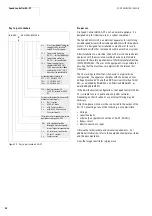
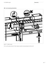
Figure 85: DIP switch/jumper
a
Jumper left, settings
a
table 12
b
Jumpers right
a
table 12
c
Information digit for service
d
DIP switches: 1 – 4 for setting current values
5 – 10 for setting additional functions
e
Jumper bottom,
a
table 12
1
1
0
OFF
2
3
4
5
1
ON
DIP
2
3
4
5
6
7
9 10
8
1
0
M
V
3
.7.1
a
b
d
e
c
Summary of Contents for Rapid Link
Page 10: ...01 08 AWB2190 1430GB 6 ...
Page 40: ...01 08 AWB2190 1430GB 36 ...
Page 48: ...01 08 AWB2190 1430GB 44 ...
Page 70: ...01 08 AWB2190 1430GB 66 ...
Page 146: ...01 08 AWB2190 1430GB 142 ...
Page 162: ...01 08 AWB2190 1430GB 158 ...