

01/08 AWB2190-1430GB
Engineering
69
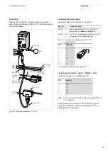
I/O assignment
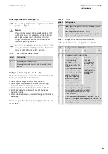
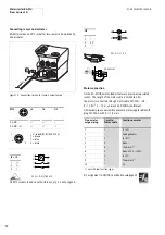
Sensor connection through M12
The sensor connection cables for inputs I3 and I4 must not be
longer than 20 m each. The sensors are supplied through the AS-
Interface
®
. Do not connect capacitive sensors. The sensors’ total
power consumption must not exceed 160 mA. The power supply
is short-circuit proof. On overload or short circuit the RA-MO
generates a group error message.
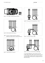
Actuator connection through M12 (RA-MO…A…)
The connection cable for output 03 must not be longer than 20 m.
The actuator is supplied by the power bus with 24 V DC. The
current consumption must not exceed 1 A. Output 03 is short-
circuit proof. On overload or short circuit the RA-MO generates a
group error message and switches off the power for output 03.
Once the fault has been rectified, you can issue a Reset command.
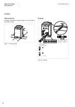
Motor cable/motor plug
If user-assembled motor connection plugs are fitted, the motor
cable for motor control unit RA-MO must not be longer than 25 m.
Selection of short-circuit devices
section “Incoming supply 400 V AC” on page 13.
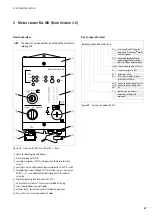
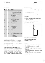
Cable routing
Do not lay the control and signal lines directly adjacent to mains
or motor cables. Avoid laying them in a common cable duct and
do not bundle them with cable ties.
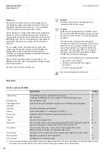
Accessories
• Motor cable SET-M3/…-HF with assembled, halogen-free
cable, 2/3/5/10 m.
• Lock shackle SET-M-LOCK for motor cables SET-M3…
• Motor connection plug SET-M3-A for user aassembly, cable
length
F
25 m
• Adapter cables for power supply through ribbon or round cable
RA-C3/C…-1,5HF
• Power plug RA-C3-PLF for user assembly for motor starter
RA-MO…/C3A
• Spare key for key-switch M22-ES-MS1.
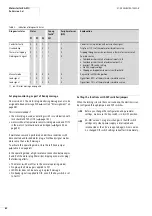
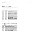
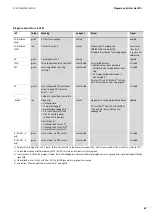
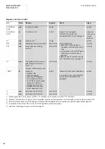
Data Bit
I/O
Meaning
DI0
I1
Automatic mode/Ready signal
0: Not ready for automatic operation
1: Ready for automatic operation
DI1
I2
Group error, see table on page 82,
keyword “Motor”
0: Fault
1: no fault
DI2
I3
external input via M12 socket
DI3
I4
0: no signal
1: Signal applied
DO0
O1
Main contactor
0: not actuated
1: actuated
DO1
O2
Reversing contactor
0: not actuated
1: actuated
DO0 + DO1
O1 + O2
Reset
0: no Reset
1: Reset
DO2
O3
Free LED signal or external output through
M12 socket
0: no signal
1: Signal applied
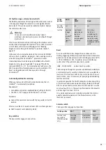
h
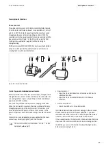
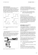
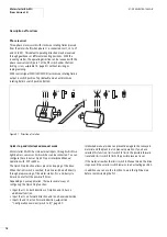
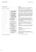
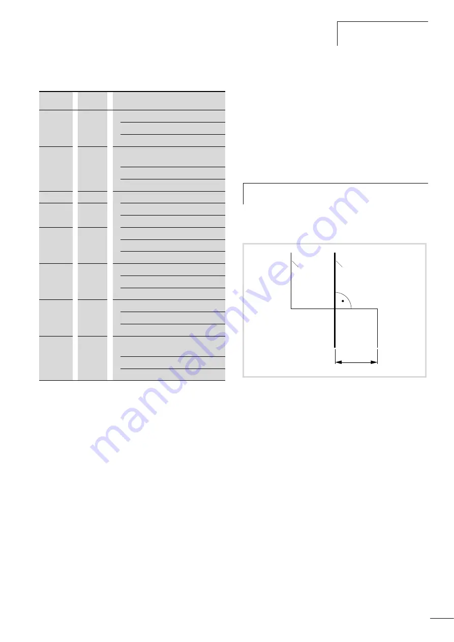
Lay the control and signal cables separately from the
mains and motor cables.
Figure 70: Crossover of signal and power cables
a
Power cable: Mains connection, motor cable
b
Control cable: AS-Interface
®
f
100
b
a
Summary of Contents for Rapid Link
Page 10: ...01 08 AWB2190 1430GB 6 ...
Page 40: ...01 08 AWB2190 1430GB 36 ...
Page 48: ...01 08 AWB2190 1430GB 44 ...
Page 70: ...01 08 AWB2190 1430GB 66 ...
Page 146: ...01 08 AWB2190 1430GB 142 ...
Page 162: ...01 08 AWB2190 1430GB 158 ...