


Motor starter RA-MO
(from Version 3.0)
01/08 AWB2190-1430GB
74
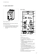
Device operation
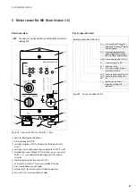
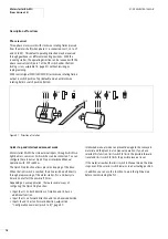
Motor control unit RA-MO is supplied ready for connection. It
allows the direct operation of a 0.09 to 3 kW, 400 V 50 Hz motor
without special technical knowledge.
You can set the following operating modes with key-switches:
• Manual (setup, commissioning, maintenance). In this mode, the
motor can amos be operated without PLC.
• Auto (continuous operation through AS-Interface
®
control).
Enable with preselected direction.
• Off or Reset”. In switch position Off the contactor actuation is
interrupted and the drive is switched off. At the same time,
setting the switch to Off resets any fault identified by the
RA-MO, such as motor overtemperature (thermistor required) or
overload. Faults are indicated by the red LED in the motor
symbol and signalled through AS-Interface
®
.
Functions through AS-Interface
®
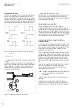
In addition to the normal control functions, Clockwise Operation
and Anticlockwise Operation and signals Automatic Operation
and Group Error, sensor signals assigned to the drive can be read
and internally processed. The configurable quick stop allows
precise stopping, for example on connection points and (eccentric
levating platforms). Interlocked manual mode can prevent
damage to the conveyed material and the plant in also manual
operation.
Through AS-Interface
®
you can also perform a Reset and read out
a detailed diagnostics status. This allows preventive maintenance
and simplifies servicing,
You can also use AS-Interface
®
to specify whether monitoring of
the motor plug (= thermistor monitoring) is part of the Group error
or Ready signal.
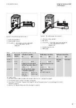
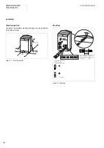
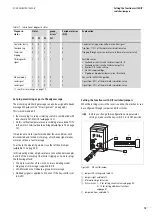
Commissioning the drive
X
Key-switch in "OFF" position
X
Selector switch REV-OFF-FWD in Off position
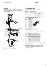
Before commissioning the motor control unit, make sure that the
motor is correctly connected and the motor cable is plugged in.
The plug M12 to the AS-Interface
®
connection must be live. The
LED ASi-POWER is lit.
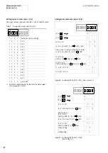
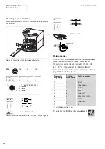
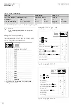
Before commissioning, the motor’s current value must be set with
the DIP switch (
section “Setting the functions with DIP
switches/jumpers”, page 79). This ensures that the motor is also
protected against overload during commissioning. When the
mains cable is connected, the load switch (disconnect control unit
RA-DI) then applies mains voltage. LED display UV on the motor
symbol indicates readiness for operation. A lit red LED in the motor
symbol indicates a group error.
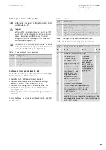
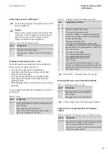
Error handling
X
Set the key-switch in the OFF position.
X
Check the DIP switch position (
X
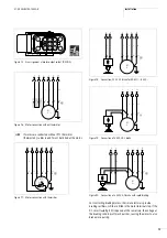
Check whether
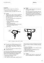
– the motor plug is plugged in.
– the thermistor is correctly connected or whether wires 6 and
7 are bridged in the motor terminal board (
a
fig. 76 and
fig. 77, page 73)
– the motor is overloaded or too hot
– there is a short circuit or an overload of sensor inputs I3 or I4
or actuator output O3.
X
Key-switch in "HAND" position
X
Selector switch REV-OFF-FWD is used to enable forward (FWD)
and reverse (REV) operation. The current selection is indicated
by LEDs REV and FWD on the motor symbol.
Safety-relevant power-off (RA-MO24V… only)
i
Caution!
Do not disonnect the motor and power plugs while they
are live.
h
Only RA-MO24V… features a safety power-off function
up to Category 2 according to EN 954-1. By isolating the
24 V at the infeed position, all RA-MO24V… devices on
one busbar run are switched off. To activate this function,
I/O fault messaging must be on the busbar run on all RA-
MO24V… units,
j
Warning!
To avoid unexpected starting after a power failure, take
the following steps:
• In automatic mode, 24 V DC or 400 V AC:
Disconnect the 24 V or 400 V and reset the actuation
command in the PLC.
• In manual mode, 24 V DC:
If a directionof rotation has been selected, the drive
does not automatically restart when power is restored.
The direction LED flashes. To continue manual
operation, a Reset command must be issued (key-
switch to OFF).
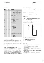
• In manual operation, 400 V AC:
Activate function “Monitoring lower current limit only
in Manual mode“ (
400 V AC fail with this setting, a group error is
generated.
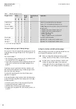
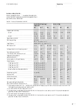
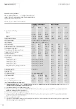
Observe the current limit values on page 78.
Summary of Contents for Rapid Link
Page 10: ...01 08 AWB2190 1430GB 6 ...
Page 40: ...01 08 AWB2190 1430GB 36 ...
Page 48: ...01 08 AWB2190 1430GB 44 ...
Page 70: ...01 08 AWB2190 1430GB 66 ...
Page 146: ...01 08 AWB2190 1430GB 142 ...
Page 162: ...01 08 AWB2190 1430GB 158 ...