


01/08 AWB2190-1430GB
Setting the functions with DIP
switches/jumpers
61
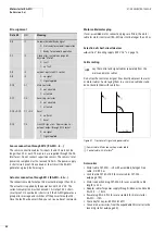
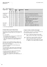
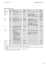
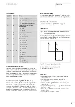
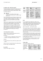
Table 3:
Function of jumper settings depending on device version
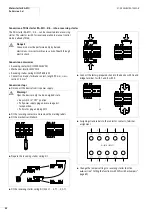
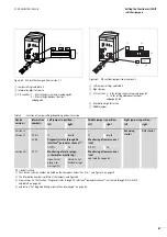
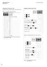
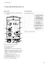
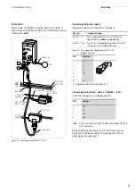
Figure 64: DIP switches/jumpers from version 2.1
a
Jumper settings
a
table 3
b
Information digit for service
c
DIP switches: 1 – 4 for setting current values
5 – 8 for setting additional functions
1
1
0
OFF
2
3
4
5
1
ON
V3.63
DIP
2
3
4
5
6
7
8
1
0
M
a
c
b
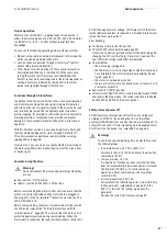
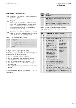
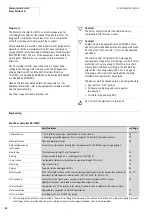
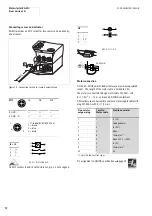
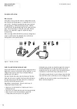
Figure 65: DIP switches/jumpers from version 2.2
a
Left jumper, settings
a
table 3
b
Right jumper
c
DIP switches: 1 – 4 for setting current values
5 – 10 for setting additional functions
d
Information digit for service
e
Middle jumper
1
1
0
OFF
2
3
4
5
1
ON
V
3
.7.1
DIP
2
3
4
5
6
7
9 10
8
1
0
M
a
b
d
e
c
Device
version
1)
Information
number
2)
Left jumper in position...
Middle jumper in position...
Right jumper in position....
left
right
left
right
left
right
Version 1.x
–
–
–
Reversing
starter
DOL starter
Version 2.1
V 3.6.3
FS
invalid
FS
invalid
V3.6.4:
Diagnostic status through AS-
Interface
®
parameter channel
3)
Monitoring of lower current
limit
Off (FS)
On
Off (FS)
On
Version 2.2
3)
V3.7.1:
Monitoring of motor plug
4)
(= thermistor monitoring)
Monitoring of lower current
limit
Open: Part of
group error
message (FS)
Closed: Part of
Ready message
DS = default setting
1) Your device’s version number is printed on the nameplate under “Ver.-No.:”,
2) The information number is printed at the jumpers,
a
figure 64
3) From version 2.2 the function “Diagnostic status through AS-Interface
®
parameter channel” is activated through DIP switch 10,
table 9 on page 63.
4)
section “Set plug monitoring as part of Ready message” on page 60.
Summary of Contents for Rapid Link
Page 10: ...01 08 AWB2190 1430GB 6 ...
Page 40: ...01 08 AWB2190 1430GB 36 ...
Page 48: ...01 08 AWB2190 1430GB 44 ...
Page 70: ...01 08 AWB2190 1430GB 66 ...
Page 146: ...01 08 AWB2190 1430GB 142 ...
Page 162: ...01 08 AWB2190 1430GB 158 ...