


Speed controller RA-SP
01/08 AWB2190-1430GB
106
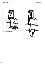
The following devices can be connected to the serial interface:
• Display unit DE5-KEY-RO3, for example for direct frequency
indication (connection cable DE5-CBL-…-ICL required).
• Keypad DEX-KEY-10 for parameterization (connection cable
DEX-CBL-…-ICS required).
With the Copy function, parameters can be read out of RA-SP
and copied to another RA-SP. This simplifies commissioning, for
example for series machines. For further information about
parameterization and operation of the DEX-KEY-10, see manual
AWB8240-1416.
• PC through connection cable DEX-CBL-2MO-PC (with built-in
RS 422/RS 232 interface converter). With the Moeller
parameterization software DrivesSoft (ftp://ftp.moeller.net/
DRIVES/SOFTWARE/) all parameters can be read and written. In
addition, parameters can be copied, saved and printed, and the
operating modes displayed graphically in a trend analyzer.
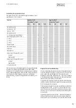
The parameters of speed control unit RA-SP2-34… are assigned
equivalent to frequency inverter DF5-340-... Basic functions
section “Parameterization”, page 114.
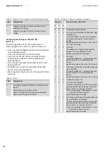
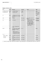
Selector switch
The key-switches engage in all positions.
Key-switch
In operating mode HAND (key-switch) start, stop and direction
reversal are performed with selector switch REV-OFF-FWD
(REV = reverse, FWD = forward, OFF = stop and reset following a
fault detected by the power module). The selected direction is
indicated by the LED on the motor.
The speed control unit is controlled through AS-Interface
®
(from
interface control unit RA-IN). The AS-Interface
®
connection must
be established. The AS-Interface
®
Power LED in the AS-Interface
®
symbol is lit. The key-switch must be in AUTO position. Selector
switch REV-OFF-FWD has no function in this case.
The key-switches engage in all positions.
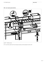
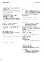
figure 113 indicates the interaction between automatic and
manual operation as well as the phase reversal switch.
Switch postion
REV
OFF
FWD
Function (with key-
switch in HAND position
only)
Anti-
clockwise
No actuation
Clockwise
Switch postion
AUTO
OFF
RESET
HAND
Key with-
drawable
yes
yes
no
Function
Operation
through AS-
Interface
®
,
Status signal to
PLC
Reset on fault
signal
(red LED in
motor symbol)
Start, stop,
direction
reversal
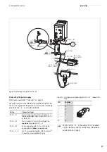
Figure 113: Controlling the speed control unit
a
Switch for setting phase reversal
b
Key-switch AUTO–OFF–HAND
c
Selector switch REV–OFF–FWD
d
Potentiometers
L
DQ0
DQ2
n
o
DQ3
DQ1
A-0-H
L-0-R
R
L
R
L1 = U, L3 = W
L1 = W, L3 = U
+ 24 V (internal)
AUTO
HAND
AS-Interface
AS-Interface
signal
AUTO
a
b
c
d
Summary of Contents for Rapid Link
Page 10: ...01 08 AWB2190 1430GB 6 ...
Page 40: ...01 08 AWB2190 1430GB 36 ...
Page 48: ...01 08 AWB2190 1430GB 44 ...
Page 70: ...01 08 AWB2190 1430GB 66 ...
Page 146: ...01 08 AWB2190 1430GB 142 ...
Page 162: ...01 08 AWB2190 1430GB 158 ...