


Speed controller RA-SP
01/08 AWB2190-1430GB
114
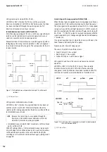
must be Low for at least 18.5 ms. The reset is performed when the
data bits are then High for at least 18.5 ms. A built-in logic circuit
prevents fault conditions.
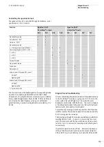
When mains power is switched on, the frequency inverter performs
a self-test. The power module detects the following errors, which
can be read through the serial interface.
• Mains overvoltage, mains undervoltage
• Overvoltage in internal DC link
• Overcurrent (overload, short-circuit, ground fault)
• EEPROM and microprocessor errors
• Overtemperature in power module
• Overtemperature in motor (with thermistor or thermal switch
only) or interruption of motor line. For RA-SP-HE… this error
message is not detected by the power module. It is available as
diagnostics status through the parameter channel,
For RA-SP-341… , RA-SP-342…, RA-SP-341(230) and
RA-SP-343(230)… the following applies:
The device’s built-in fuses for the DC air solenoid is not reported
separately. For testing, a voltage measurement between pin 4 and
pin 6 is required. This test must be performed by a trained
electrician.
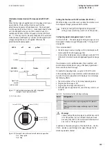
Auto configuration for servicing
When you replace a RA-SP with an identical device, the AS-
Interface® is automatically transferred.
Requirement:
• Auto-addressing mode is enabled (default setting for RA-IN).
• The 400 V~ supply and AS-Interface® are active.
Procedure:
X
Make the plug-in connections to the new RA-SP…
The key-switch is in its Off position. After no more than 0.5
seconds all error LEDs must have gone out.
X
Select HAND (manual) or AUTO operating mode.
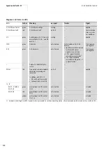
Parameterization
The parameters of the frequency inverter DF5 are described in
manual AWB8230-1412.
The descriptions below include only those parameters that are
applicable for use of the RA-SP in the Rapid Link system.
The parameters can be changed only with the keypad DEX-KEY-10
or the Moeller parameterization software Drive-Soft
(
a
page 105).
The speed control unit RA-SP is factory-configured for operation in
the Rapid Link system. Depending on your application, individual
functions of the RA-SP can be adapted to the assigned drive in one
of several ways:
• With a PC running the Moeller parameterization software
Drives Soft
• Through the keypad DEX-KEY-10
The PC or keypad is connected through the serial RS 422 port
(
page 103), which is located under the screw cover.
The default settings of the RA-SP are:
• Acceleration time = 10 s
• Delay time = 2 s
• PTC monitoring enabled:
– On RA-SP2-34… PTC monitoring is performed in the power
module and is enabled through digital input 5.
– On RA-SP-HE… monitoring is independent of the power
module.
• Reference frequency 1 = 30 Hz
• Reference frequency 2 = 40 Hz
• Reference frequency 3 = 50 Hz
• Reference value potentiometer
n
0
(under the screw cover on the device front), about 10 Hz
h
Caution!
The processor of the RA-SP contains parameters of
frequency inverter DF5, which can not be activated with
the Rapid Link system. Incorrectly parameter settings can
lead to undefined operating states and malfunction.
h
Caution!
The parameters listed in this section must be changed
only by trained personnel and according to the
instructions in manual AWB8230-1412.
h
Caution!
Do not connect or disconnect the connection cable
between HMI device and speed control unit in operation,
as this could cause unpredictable drive behaviour.
Summary of Contents for Rapid Link
Page 10: ...01 08 AWB2190 1430GB 6 ...
Page 40: ...01 08 AWB2190 1430GB 36 ...
Page 48: ...01 08 AWB2190 1430GB 44 ...
Page 70: ...01 08 AWB2190 1430GB 66 ...
Page 146: ...01 08 AWB2190 1430GB 142 ...
Page 162: ...01 08 AWB2190 1430GB 158 ...