Speed controller RA-SP
01/08 AWB2190-1430GB
100
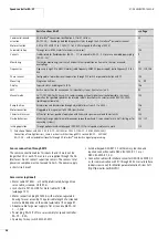
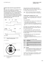
If motors are connected without PTC thermistor or thermal switch,
cables 7 and 8 must be linked at the motor; otherwise the RA-SO
issues a fault message.
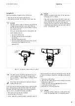
Figure 105: Examples of motor connections
PES
5
8
1
7
3
PE
T1
T2
M 3
h
i
U
V
W
PE
e
PES
PES
5
8
1
7
3
PE
T1
T2
M 3
h
i
U
V
W
PE
e
PES
F
25 m
/ 400 V
230
3.2 / 1.9 A
0.75
S1
0.79
ϕ
cos
kW
rpm
1430
50 Hz
U1
V1
W1
W2
U2
V2
/ 690 V
400
1.9 / 1.1 A
0.75
S1
0.79
ϕ
cos
kW
rpm
1430
50 Hz
U1
V1
W1
W2
U2
V2
PES
5
8
1
7
3
PE
T1
T2
M
3
h
U
V
W
PE
e
PES
PES
5
8
1
7
3
PE
T1
T2
M 3
h
i
U
V
W
PE
4
6
B1
B2
e
PES
RA-SP2-341/-343-…
RA-SP2-341/-343(230)-…
h
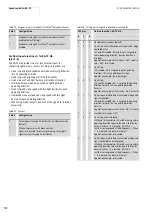
The motor circuit must be laid out for the rated
operational voltage (400 V).
i
Warning!
If motors are used whose insulation is not suitable for
operation with RA-SP, the motor may be destroyed.
i
Warning!
Risk of destruction of the motor through the RA-SP’s
frequency-controlled output if braking units or braking
rectifiers are connected directly to the motor’s terminals.
Summary of Contents for Rapid Link
Page 10: ...01 08 AWB2190 1430GB 6 ...
Page 40: ...01 08 AWB2190 1430GB 36 ...
Page 48: ...01 08 AWB2190 1430GB 44 ...
Page 70: ...01 08 AWB2190 1430GB 66 ...
Page 146: ...01 08 AWB2190 1430GB 142 ...
Page 162: ...01 08 AWB2190 1430GB 158 ...

