


55M3500AQE-C
55M3500AQE-C
WYLIE’s I3500 QuICk REfEREnCE shEEt
WYLIE’s I3500 QuICk REfEREnCE shEEt
operating buttons presentation
Page 2
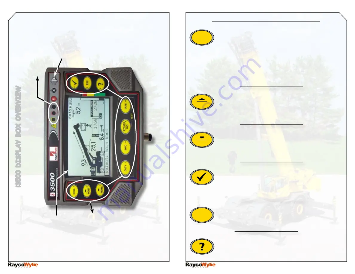
i3500 D
isp
La
Y
bo
X
o
V
er
V
ie
W
operating buttons
W
arning Lig
H
ts
interna
L
bu
ZZ
er
grap
H
iC
a
L
D
isp
La
Y
Page 1
MODE BUTTON : Shows system’s modes. Press
this button to choose one of these operating
modes:
-Normal mode
-Limits Setting or Range Limiting mode
-System Set Up mode
-Diagnostic mode
-Calibration mode (password protected).
MODE
1
Hoist / sCroLL up button : shows hoist menu
for selection of the hoist currently in use. Also
used to scroll up in menus or increase editable
values.
HOIST
2
PARTS / SCROLL DOWN BUTTON : Shows parts
of line (falls) menu for selection of the number of
parts currently in use. Also used to scroll down in
menus or decrease modifiable values.
PARTS
3
SELECT BUTTON : Used to select a highlighted
item in a menu. In normal mode, use this button
to select the information displayed in one of the
pull down menus.
4
ESCAPE BUTTON : Used to close a menu or cancel
the modification of a value. Push it several times
to return to normal mode.
ESC
5
HELP BUTTON : This button will show the problem
source when a fault is detected by the system.
Push it to see a description of the problem.
6


