background image

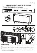
TIPPING RESTRAINTS KIT INSTALLATION GUIDANCE

AA1 x 2

AA2 x 4

AA3 x 4

AA4 x 4

2

3

4

AA2

AA1

AA1

AA3

Different wall materials require unique wall fasteners. 
The wall plugs (AA2) and screws (AA3) are designed for fixing to concrete walls only.
Please consult your local hardware store to ensure you are using the correct hardware for your wall type. 

4

5

Grids Surface

8-10cm

8-10cm

AA1

AA4

1

1. Attach bracket (AA1) securely to the back top of the furniture using screw (AA4) provided. Allow 8 - 10 cm from each side.
2. Please make a hole for wall plugs position on the wall and minimum 15 mm below bracket secured to the back of unit attach the wall plugs 
(AA2).
3. Locate the other bracket (AA1) on the wall over wall plugs (AA2). Place furniture into position so both brackets (AA1) are vertically in the 
line.
4. Lace the end of the restraints strap through the larger hole in each brackret. Ensure the restraints strap with grids surface facing the inner 
loops. Bring both ends together and slide the flat end through the locking end and draw it through until all slack is removed.
5. Make sure that the strap is securely laced & locked.

Installation Instructions :

Summary of Contents for Soma EEI-6042

Page 1: ...Questions Contact us 609 256 9000 cs modway com www modway com ...

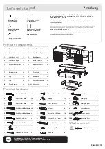
Page 2: ...illips P x12 Screw M 8 x 39 mm Q x4 Screw Cap Ø15 mm R x8 Shelf Pin S T x1 x4 Allen Key Sliding Top Sliding Bottom U x4 V x2 Silicon Bumper Drawer Runner RM35A x3 Mounting Plate PM2 x2 1 2 3 4 19 6 7 7 8 8 9 9 15 15 16 16 17 18 18 18 5 LC16A1 LC16A1 PAGE 2 OF 15 Only use hand tools to assemble this item Do not use power tools Do not tighten bolts or screws completely until all hardware is lined up...

Page 3: ...This is a permanent label Do not remove ATTENTION Les enfants sont morts de basculement dans les meubles Réduire les risques de renversement de meubles TOUJOURS installer la retenue de renversement fournie NE JAMAIS installer de téléviseur sur ce produit Ne JAMAIS LAISSER les enfants se tenir debout grimper ou s accrocher aux tiroirs aux portes ou aux étagères NE JAMAIS ouvrir plus d un tiroir à l...

Page 4: ... 3 x 3 RM35A RM35A O O K G G K 50 60 mm G K x12 Screw M 3 5 x 15 5 mm G x12 Wedge K x18 Screw M 3 5 x 13 mm O x3 Drawer Runner HARDWARE RM35A x20 Cam Bolt Ø6 x 35 mm A HARDWARE COMPONENTS x1 Top Board 1 x1 Bottom Board 2 A A 1 2 A ...

Page 5: ... Dowel Ø8 x 30 mm D HARDWARE COMPONENTS x1 Side Board Right 4 x1 Side Board Left 3 x2 Front Skirt 17 x3 Back Board 18 x8 Wood Dowel Ø8 x 30 mm D x18 Screw M 6 x 10 5 mm N x3 Drawer Runner HARDWARE COMPONENTS x1 Center Board Right 5 x1 Center Board Left 19 RM35A D RM35A RM35A N N 19 ...

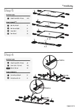
Page 6: ...5 Step 7 Step 8 17 x2 Front Skirt COMPONENTS x4 Cam Lock Ø15 mm B HARDWARE COMPONENTS x1 Top Board 1 x1 Side Board Left 3 x1 Side Board Right 4 x1 Center Board Right 5 x1 Center Board Left 19 1 3 4 5 19 B B 17 17 ...

Page 7: ...PAGE 7 OF 15 Step 9 Step 10 x4 Cam Lock Ø15 mm B HARDWARE B B 18 18 18 x6 Cam Lock Ø15 mm B HARDWARE COMPONENTS x3 Back Board 18 B B ...

Page 8: ...PAGE 8 OF 15 Step 11 Step 12 Q Q A A x10 Cam Bolt Ø6 x 35 mm A Q x4 Screw Cap Ø15 mm HARDWARE x6 Cam Lock Ø15 mm B x8 Screw M 7 x 50 mm F x1 Allen Key S HARDWARE COMPONENTS x1 Bottom Board 2 B B F F S 2 ...

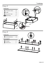
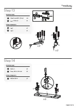
Page 9: ... D D 9 8 L L L Step 14 J x 2 7 J H x4 Bracket H x8 Screw M 4 5 x 12 5 mm J HARDWARE COMPONENTS x2 Bottom Skirt 2 7 x16 Wood Dowel Ø8 x 30 mm D x4 Floor Protector L HARDWARE COMPONENTS x2 Leg 1 8 x2 Leg 2 9 9 8 Unplug the dowel 9 8 ...

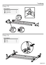
Page 10: ...Step 15 PAGE 10 OF 15 7 6 7 7 6 6 Step 16 9 9 8 8 x2 Leg 1 8 9 x2 Leg 2 COMPONENTS x2 Bottom Skirt 1 6 7 x2 Bottom Skirt 2 COMPONENTS ...

Page 11: ...Step 17 PAGE 11 OF 15 D Step 18 B B x10 Cam Lock Ø15 mm B HARDWARE x12 Wood Dowel Ø8 x 30 mm D HARDWARE ...

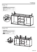
Page 12: ...Step 19 PAGE 12 OF 15 I S Step 20 J PM2 PM2 J x8 Screw M 4 5 x 12 5 mm J x2 Mounting Plate HARDWARE PM2 x4 Screw M 6 4 x 35 mm I x1 Allen Key S HARDWARE ...

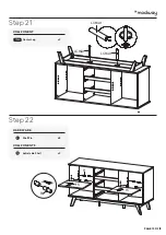
Page 13: ...Step 21 PAGE 13 OF 15 LC16A1 LC16A1 LC16A1 15 15 R R Step 22 x8 Shelf Pin R HARDWARE COMPONENTS x2 Adjustable Shelf 15 x2 Center Leg COMPONENT LC16A1 ...

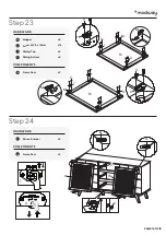
Page 14: ...16 V V U T Step 24 x2 Silicon Bumper V HARDWARE COMPONENTS x2 Frame Door 16 x4 Stopper M x16 Screw M 3 5 x 13 mm O x4 Sliding Top T x4 Sliding Bottom U HARDWARE COMPONENTS x2 Frame Door 16 O T M M U 16 16 O T M M U T O U O M M ...

Page 15: ...ou s accrocher aux tiroirs aux portes ou aux étagères NE JAMAIS ouvrir plus d un tiroir à la fois Placez les articles les plus lourds dans le tiroir le plus bas Ceci est une étiquette permanente Ne pas enlever Los niños han muertopor vuelco de muebles Para reducir el riesgo de vuelco de muebles SIEMPRE instale la restricción del vuelco provista NUNCA cologue un televisor en este producto NUNCA per...

Page 16: ...vided Allow 8 10 cm from each side 2 Please make a hole for wall plugs position on the wall and minimum 15 mm below bracket secured to the back of unit attach the wall plugs AA2 3 Locate the other bracket AA1 on the wall over wall plugs AA2 Place furniture into position so both brackets AA1 are vertically in the line 4 Lace the end of the restraints strap through the larger hole in each brackret E...

Reviews: