Modine Manufacturing MT112 Installation And Service Manual Download Page 7

7

START-UP PROCEDURE

Pilot Flame Adjustment (Intermittent Pilot and
Millivolt Standing Pilot control systems – Control
Codes 04, 08, 27, and 67

The pilot burner is orificed to burn properly with an inlet

pressure of 7-14" W.C. on natural gas and 11-14" W.C. on

propane gas, but final adjustment must be made after

installation. If the pilot flame is too long or large, it is possible

that it may cause soot on the burner assembly. If the pilot flame

is shorter than shown, it may cause poor ignition and result in

the controls not opening the combination gas control. A dirty

pilot orifice may cause a short flame. Pilot flame condition

should be observed periodically to assure trouble-free

operation.

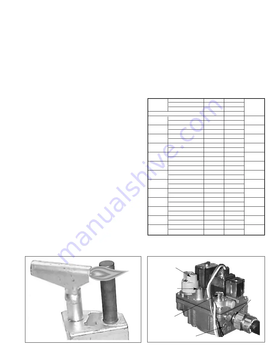
To adjust the pilot flame:

1. Create a call for heat from the thermostat.
2. Remove the cap from the pilot adjustment screw. For

location, see the combination gas control literature supplied

with unit.

3. Adjust the pilot flame length by turning the screw in or out

to achieve a soft steady flame 3/4" to 1" long and

encompassing 3/8"-1/2" of the tip of the flame sensing rod

or power-pile (See Figure 7.1).

4. Replace the cap from the pilot adjustment screw.

Main Burner Adjustment

The gas pressure regulator (integral to the combination gas

control) is adjusted at the factory for average gas conditions. 

It is important that gas be supplied to the heater in accordance

with the input rating on the serial plate. Actual input should be

checked and necessary adjustments made after the heater is

installed. Over-firing, a result of too high an input, reduces the life

of the appliance and increases maintenance. Under no

circumstances should the input exceed that shown on the serial

plate.

Measuring the manifold pressure is done at the test port on the

main gas valve on the unit (See Figure 7.2).

To adjust the manifold pressure:

1. The correct manifold pressure is 6" W.C. for natural gas

and 10" W.C. for propane gas. Adjust the main gas

pressure regulator spring to achieve the proper manifold

pressure (see Figure 7.2).

2. Move the field installed manual shut-off valve to the “OFF”

position.

3. Remove the 1/8" pipe plug in the gas valve adjacent to the

manifold and attach a water manometer of “U” tube type

that is at least 12" high.

4. Move the field installed manual shut-off valve to the “ON”

position.

5. Create a call for heat from the thermostat.
6. After adjustment, move the field installed manual shut-off

valve to the “OFF” position and replace the 1/8" pipe plug.

7. After the plug is in place, move the field installed manual

shut-off valve to the “ON” position and recheck pipe plugs

for gas leaks with a soap solution.

Figure 7.1 
Correct Pilot Flame (Millivolt Powerpile shown)

Figure 7.2 
Gas Valve Features

Pilot Adjustment
Screw (Under Cap) 

Regulator Adjustment
Screw (Under Cap)

Plugged Outlet
Pressure Tap

Pilot Line
Connectio

n

Control
Knob

Type of Gas

Natural

Propane

Model

Btu/Ft.

3

1040

2500

No. of 

Size

Specific Gravity

0.60

1.53

Orifices

Manifold Pressure In. W.C.

6.0

10

MT-28

cfh

26.4

-

1

Orifice Drill Size

#43

-

MT-30

cfh

28.8

12.0

1

Orifice Drill Size

#42

#52

MT-33

cfh

32.2

-

1

Orifice Drill Size

#41

-

MT-56

cfh

52.9

-

2

Orifice Drill Size

#43

-

MT-60

cfh

57.7

24.0

2

Orifice Drill Size

#42

#52

MT-66

cfh

64.4

-

2

Orifice Drill Size

#41

-

MT-84

cfh

79.3

-

3

Orifice Drill Size

#43

-

MT-90

cfh

86.5

36.0

3

Orifice Drill Size

#42

#52

MT-99

cfh

96.6

-

3

Orifice Drill Size

#41

-

MT-112

cfh

105.8

-

4

Orifice Drill Size

#43

-

MT-120

cfh

115.4

48.0

4

Orifice Drill Size

#42

#52

MT-132

cfh

128.8

-

4

Orifice Drill Size

#41

-

MT-160

cfh

153.8

64.0

4

Orifice Drill Size

#38

#49

Table 7.1 
Manifold Pressure and Gas Consumption

Summary of Contents for MT112

Page 1: ... LEAVE THE JOB Inspection on Arrival 1 Inspect unit upon arrival In case of damage report it immediately to the transportation company and your local sales representative 2 Check rating plate on unit to verify that the power supply meets available electric power at the point of installation 3 Inspect unit upon arrival for conformance with description of product ordered including specifications whe...

Page 2: ...s are contained in the current edition of ANSI NFPA 409 or in accordance with the enforcing authority for Canada Public Garages Approval requirements are contained in the current edition of NFPA 88B CAN CGA B149 for Canada Parking Structures Approval requirements are contained in the current edition of NFPA 88A General All installations must be in accordance with the current edition of ANSI Z 223 ...

Page 3: ... 120 132 54 48 45 120 MT160 60 54 51 136 Model No 3 Be sure that the minimum clearances to combustible materials and for serving are maintained The minimum clearances to combustibles are shown in Table 3 2 4 Mounting height measured from the bottom of unit at which heaters are installed is critical Please refer to mounting height information in Table 4 1 5 Do not locate units in areas where chlori...

Page 4: ... TO SUPPORT WEIGHT OF THE HEATER Horizontal Plane 10 Minimum 35 Maximum Mounting Height Minimum Clearance to Combustible Materials Stacking Height Figure 4 1 Combustible Material Clearances 10 MIN 35 MAX REAR BELOW THE GAS MANIFOLD AND CONTROLS MUST BE LOCATED AT THE LOW END OF THE HEATER TOP NOTE Gas manifold MUST be located on the low side of the heater Combustion Ventilation Air Requirements Ma...

Page 5: ...e heaters to the gas supply and to avoid placing stress on the gas supply line 6 When pressure leak testing pressures above 14 W C 1 2 psi close the field installed shut off valve disconnect the appliance and its combination gas control from the gas supply line and plug the supply line before testing When testing pressures 14 W C 1 2 psi or below close the manual shut off valve on the appliance be...

Page 6: ...ke of fresh air and exhaust of products of combustion 4 Perform a visual inspection of the unit to make sure no damage has occurred during installation 5 Recheck the gas supply pressure The inlet pressure to the unit must be 7 14 W C for natural gas and 11 14 W C for propane gas The gas supply pressure must never exceed 14 W C If the pressure exceeds 14 W C a gas pressure regulator must be added u...

Page 7: ...ng the manifold pressure is done at the test port on the main gas valve on the unit See Figure 7 2 To adjust the manifold pressure 1 The correct manifold pressure is 6 W C for natural gas and 10 W C for propane gas Adjust the main gas pressure regulator spring to achieve the proper manifold pressure see Figure 7 2 2 Move the field installed manual shut off valve to the OFF position 3 Remove the 1 ...

Page 8: ...lame sensor proves ignition and stops the spark igniter from sparking At the same time the main gas valve is opened and the ceramic burner is lit The unit continues to operate until the thermostat is satisfied at which time the main gas and pilot gas valves are closed 100 and the unit shuts off Millivolt Self Energizing with Standing Pilot and 100 Safety Shutoff Gas Controls Control Codes 26 and 6...

Page 9: ...eater and close the gas supply valve installed adjacent to the heater With an air hose regulated to 15 psig maximum blow off any dust and dirt that has accumulated on the heater by blowing across the ceramic burner not directly at the ceramic burner Do not insert the air hose into the inlet of each venturi tube Burner Orifice Remove each burner orifice clean and reinstall on the heater manifold Dr...

Page 10: ...ostat wiring 5 Verify wiring compared to diagram 6 Manual valve closed on combination gas valve 6 Turn knob to ON position on combination gas valve Direct spark fails to ignite 1 Electrode improperly located 1 Relocate to correct position main burner s 2 Electrode ceramic cracked 2 Replace electrode 3 Electrode wire is loose broken or frayed 3 Reconnect loose wire or replace broken or frayed wire ...

Page 11: ...l unit s or other heat source must be added Gas odor 1 Loose pipe connection 1 Check all connections with a soap solution and tighten as necessary Control assembly 1 Heater not mounted correctly 1 Angle to be 10 to 35 from horizontal overheating 2 Heater mounted too close to ceiling 2 Check to maintain proper top clearance Trouble Possible Cause Possible Remedy For Servicing If a qualified service...

Page 12: ...IVE OF ALL OTHER REMEDIES PROVIDED BY LAW IS LIMITED TO REPAIR OR REPLACEMENT AT THE FACTORY OF SELLER ANY HEAT EXCHANGER CONDENSER OR BURNER WHICH SHALL WITHIN ONE YEAR FROM DATE OF FIRST BENEFICIAL USE BY BUYER OR ANY OTHER USER WITHIN ONE YEAR FROM DATE OF RESALE BY BUYER IN ANY UNCHANGED CONDITION OR WITHIN EIGHTEEN MONTHS FROM DATE OF SHIPMENT FROM SELLER WHICHEVER OCCURS FIRST BE RETURNED TO...

Reviews: