19
MCP15-500.9
27. For units equipped for dual power supply sources, the unit
should be started separately on the main power feed and
again on the auxiliary power feed to verify proper unit and
control operation.
Note: Units equipped for dual power supply sources have the
unit power wiring separated into two circuits as follows:
Circuit #1
• Compressors
• Condenser fans
• Electric heating section (if applicable).
• Energy recovery wheel (if applicable)
Circuit #2
• Main unit controller
• Supply fan
• Dampers
• Gas heating section (if applicable)
• Exhaust fan (if applicable)
• Energy recovery wheel bypass damper (if applicable)
When operating in a full power state with the main power
feed, both Circuit #1 and Circuit #2 should be powered.
When operating in a low power state with the auxiliary power
feed, only Circuit #2 should be powered.
Blower Adjustments
The units are designed for ease of airflow adjustments, within a
range, for field balancing against actual external static pressure
conditions. If the static pressure external to the unit is above
or below the original design point for the unit, the blower will
deliver an airflow volume that is lower or higher than required.
When equipped with the building exhaust option (with or
without energy recovery), the air balancing must be performed
for both the main unit supply fan, as well as the exhaust fan.
The blower speed (supply and/or exhaust blowers) may be
adjusted to achieve the desired air volume, provided:
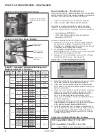
• The allowable temperature rise range and the maximum
supply air temperature for heating is not exceeded as
shown in Table 20.1, and
• The airflow is within the allowable limits shown on the
serial plate for both heating and cooling, and
• The total static pressure does not exceed the limit shown
on the unit serial plate, and
• It is within the range of adjustability for the unit, and
• The motor amp draw must not exceed the motor
nameplate rating.
The blower speed adjustment method is dependent on the
following configurations:
• Direct Drive
where the blower is driven directly by the
motor as seen in Figure 20.1. This is the current
standard supply fan configuration for all units.
• Belt Drive
where the blower is driven by the motor with a
belt and sheaves as seen in Figure 20.2. This is the
current standard exhaust fan configuration (if equipped)
for all B- and C-Cabinet sized units. It was also used on
supply fans for units shipped before 2018.
Once the blower/motor configuration of the unit is determined,
follow the appropriate instructions in the sections on the
following pages.
17. Check that the evaporator drain pan drain trap has been
primed with water.
18. Turn on power to the unit at the disconnect switch.
Note:
Units include one blower door switch per access
door (one on B- and C-Cabinet, two on D-Cabinet) that are
factory installed inside the blower access section door(s).
When a blower section door (supply and/or exhaust) is
opened, the switch is opened and interrupts power to the
low voltage circuit and de-energizes the blower motor
controller. D-Cabinet units also have the same switches
on the evaporator/hot gas reheat coil access sections.
19. Check the Carel microprocessor controller and supply fan
blower motor for electrical operation. If the unit is equipped
with the optional building power exhauster module (with or
without energy recovery), check the blower motor for
electrical operation. If these do not function, recheck the
wiring diagram. Check to ensure that none of the Control
Options (for example, smoke detector, etc.) have tripped.
20. Check to make sure that the outside air inlet dampers (and
return air dampers if equipped) operate properly without
binding.
21. If the unit is equipped with power exhaust (model Digit
7=B, C, E, or F) or barometric relief dampers (Digit 7=R),
check to ensure the dampers move freely and do not bind
when manually opened and closed. Refer to Figure 57.1.
22. Check that the supply power wiring is wired with the
correct phase rotation. For units equipped for dual power
supply sources, correct phase rotation must be verified on
both the main feed and the auxiliary feed. Incorrect phase
rotation can damage the equipment.
The supply fan variable frequency drive will correct the
phase rotation for the supply fan, but will not correct the
phase rotation for the rest of the unit, therefore observing
the supply blower wheel rotation direction is not an
accurate indicator of correct phase rotation. Scroll
compressors will only compress in one rotational direction.
Verification of proper rotation direction is made by
observing that suction pressure drops and discharge
pressure rises when the compressor is energized. Reverse
rotation will result in no pressure differential as compared
to normal values. There is no negative impact on
durability caused by operating the compressors in the
reversed direction for a short period of time (under one
hour) but should not be allowed to operate longer than the
time it takes to verify rotation. If the compressor is rotating
in the opposite direction, the phase reversal must be
corrected by changing the incoming power feed legs at the
supply to the unit, NOT at the compressor. Recheck for
proper rotation.
23. Check the blower speed (rpm). Refer to Blower
Adjustments for modification.
24. Check the motor speed (rpm).
25. Check the motor voltage. On three phase systems, check to
make sure all legs are in balance.
26. Check the motor amp draw to make sure it does not exceed
the motor nameplate rating. Check all legs to ensure system
is balanced.
START-UP PROCEDURE - CONTINUED


