12
5-572.10
ELECTRICAL CONNECTIONS
Evaporative Cooler Installation
For units equipped with an evaporative cooler (Model Digit
22=D), refer to Installation and Service Manual - Evaporative
Coolers (Literature 5-588).
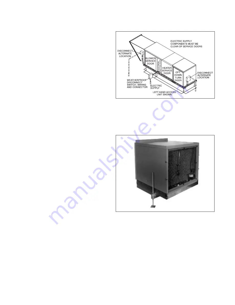
Figure 12.1 - Recommended Accessory Field
Installed Disconnect Switch Mounting Locations
9. Depending on the configuration of the unit controls,
there may be sensors that are field installed. Review the
unit ordered to verify that the sensors supplied match
the configuration of the unit. The following are sensors
that may be included for field installation (for installation
instructions, refer to the instructions included with the
individual sensors):
• Supply Air Temperature Sensor
This sensor is required on all units and is mounted in the
supply air ductwork downstream of the unit discharge.
• Outdoor Air Sensor
This sensor is required on all units except 100% return air
units. Depending on the unit configuration, the sensor
may be duct mounted or remote mounted.
• Return Air Sensor
This sensor is required on all units that have a mixture of
outside and return air. The sensor is mounted in the
return air ductwork.
• Space Temperature/Humidity Sensor
This sensor is required on all units that have space
temperature/humidity reset control.
• Building Pressure Sensor
This sensor is required on all units that have space
pressure control, either through modulating dampers or
variable frequency drive control on the supply air blower.
• Duct Pressure Sensor
This sensor is required on all units that have duct
pressure control through variable frequency drive control
on the supply air blower.
• Space CO
2
Sensor
This sensor is required on all units that have demand
based ventilation control based on space CO
2
concentration.
• Duct Mounted Smoke Detector
This sensor is mounted in the supply air or return air
ductwork.
For further instructions on the above sensor(s), refer to
the installation instructions that shipped with the
sensor(s).
10. Make sure all multi-voltage components (motors,
transformers, etc.) are wired in accordance with the power
supply voltage.
11. The power supply to the unit must be protected with a
fused or circuit breaker disconnect switch. Refer to the
Factory Mounted Option Locations (Figure 22.1) for the
factory mounted disconnect switch location and then
review the unit to determine if a factory installed dead
front disconnect switch was provided. Accessory field
installed disconnect switches should be mounted where
required by the National Electric Code as shown in Figure
12.1. For fusible disconnect switches, refer to the Model
Identification plate for the fuse size and type.
12. The power supply must be within 5% percent of the voltage
rating and each phase must be balanced within 2 percent
of each other. If not, advise the utility company.
13. All outdoor electrical connections must be weatherized to
prevent moisture from entering the electrical compartment.
Figure 12.2 - Evaporative Cooler (Model Digit 22=D)


