


21
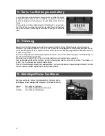
14. Servo reverse
Depending on the installation of the servos and the linkage,
it might become necessary to invert the rotational direction of individual servos. For
this purpose, the transmitter is equipped with a servo reverse switch (see ill. 8) for
each servo.
For normal rotational direction, put all switches in to upper position (NOR). If one or
more servos rotate in the wrong direction, you can individually switch the rotational
direction of each servo (REV).
15. Trimming
Except for the motor control, the control sticks are kept in centre position (neutral position) by springs.
The trim sliders (see ill. 1, pos. 2, 5, 10 and 12) allow you to sensitively adjust the centre position of the individual servos in both
directions. This enables you during operation to adjust your model plane to fly perfectly straight.
After landing, the linkage rods are moved so that the trim levers are in centre position but the model is aligned to fly straight.
The throttle trim (see ill. 1, pos. 15) is intended for idle position of combustion motors.
When the throttle control stick is in idle position (see ill. 4a), you should be able to adjust idle position ideally using the trim slider (see
ill. 1, pos. 15).
When the trim slider is all the way down, the throttle servo must close the carburettor completely. This way, you can switch off the
combustion motor using the remote control.
16. Model-specific functions
Use selection switch 1 to select model-specific functions.
The selection switch allows you to select predefined settings depending on the mod-
el used.
Airplane
to be used with planes
V-Tail
to be used with flying models with a V-tail
3D Mixing
to be used with 3D helicopters
Summary of Contents for MC50
Page 50: ...47 ...