HISTORY
2
HISTORY
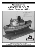
The original model plans and kit of the
Despatch No. 9
were developed in 1949 by John Shedd, the original owner of
Model Shipways in Bogota, New Jersey. These early plans and the kit have been updated with more detail and reissued
by Model Shipways, Inc. and sold by Model Expo, a division of Model Shipways. New instructions are provided along
with a more complete set of supplies for building the model. The fittings are now cast from lead-free Britannia metal
and laser-cut wood parts have been added.
The
Despatch
was constructed from an Army design; 85' Motor Tug designated Army ST (small tug). The original
design plans for the tug are in the Army Transportation Museum in Fort Eustis, VA. The Museum also has a model of
the Army tug on display. There are some differences between the Army tug design and the
Despatch,
changes required
by the owner no doubt. Primarily, the
Despatch
has a different towing winch and capstan, and some minor differences
in the deck house compartments. The Army version also has railings on the pilot house top and two machine guns, and
there is a lifeboat carried on the upper deck.
To incorporate the differences between the Army version and
Despatch,
John Shedd obviously has access to plans and
information specific to
Despatch.
Unfortunately, none of the original information could be found.
There are two other known tugs built from the Army design. The
Messenger
was built in 1944 in New Orleans as an
Army tug, but in 1946 was acquired by the Coast Guard. Likewise, the
Angels Gate
started out as an Army tug, but
soon became a commercial tug in California. What is nice about the
Angels Gate
is the fact that it is still around. The
tug has been restored and is a floating exhibit at the Los Angeles Maritime Museum. The tug is as built by the Army,
except the machine guns have been removed. There are a number of photos of the tug on the Museums web site.
Brief History ................................................................1
Before You Begin ..........................................................3
How To Work With The Plans & Parts ........................3
What You’ll Need to Start Construction .......................3
Painting........................................................................4
Stage A: Shaping the Pre-Carved Hull
1. Using the Templates .................................................4
2. Carving the Hull ......................................................4
3. Carving the Bulwarks ...............................................5
4. Deckhouse Carving ...............................................7-8
Stage B: Completing the Basic Hull Structures
1. Installing the Keel & Stem........................................6
2. Installing the Sternpost, Prop Shaft Tube Fairing,
& Propeller...............................................................6
3. Installing the Rudder Skeg & Rudder....................6-7
4. Cutting Out & Detailing the Freeing Ports ..............7
5. Installing Bulwark Brackets, Stiffeners, Cap Rail,
Quarter Bitts, Chocks, & Hawse Pipe Lips...............7
6. Installing the Outboard Pipe Fenders .......................7
7. Constructing the Deckhouse .................................7-8
Stage C: Mounting the Hull
1. Mounting Board with Two Pedestals.........................8
2. Launching Ways .......................................................8
Stage D: Adding the Hull Details
1. General Notes...........................................................9
2. Windows, Airports, & Doors....................................9
3. Running Lights, Flagstaff, & Mast............................9
4. Ladders, Upper Deck Railing & Hand Rails.............9
5. Horn, Searchlight, Bell, Ventilator, & Life Ring .......9
6. Deckhouse Name Board & Lettering........................9
7. Stern Grating............................................................9
8. Bow Chock, Cleats, and Manholes .........................10
9. Capstan & Towing Machine...................................10
10. Air Vents ..............................................................10
11. Log Fenders & Bow Bumper ................................10
12. Anchor .................................................................10
13. Final Touches........................................................10
Bibliography...............................................................11
Construction Stages & Table of Contents
Construction Stages & Table of Contents


