Interface specifications
10. Interface specifications
This section describes the specifications of the top application interface.
NOTICE
Read
before using the electrical interface.
MiR500 has five electrical interfaces divided into two groups:
•
• Power
• GPIO
• Ethernet
•
• Auxiliary Emergency Stop
• Auxiliary Safety Functions
To see the locations of the interfaces on the robot, see section
10.1. General purpose interfaces
This section describes the general purpose interfaces located in the left-hand side compartment on the top side of
MiR500.
Power
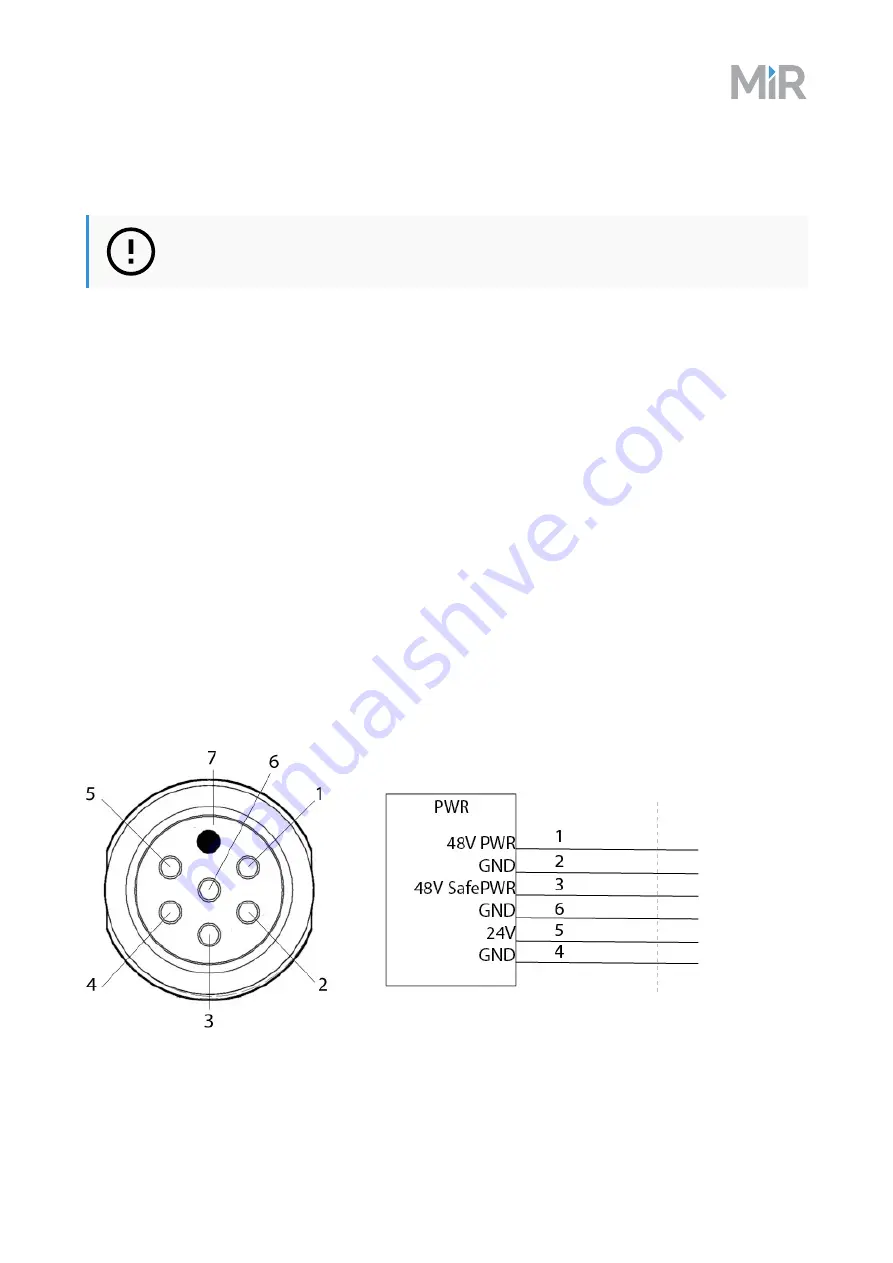
An auxiliary power connection for top applications is provided in the top left-hand side compartment. See
for more information.
Pin numbers: female connector viewed from the front (left) and wiring diagram (right).
MiR500 user guide, 2019/03, rev.1.1
65


