www.mo-sys.com
21
XR engine setup
Livelink Setup
Create a livelink subject for the tracking.
Follow the same procedure as described in
Render Node livelink setup.
Level Setup
–
actors used
Start from
XRsample
level, which graphically
explains basic components used.
Similar to the nDisplay setup the level
structure content is stored in a separate
level, which is a sublevel to the main
persistent level containing the tracked
camera and a map of the LED screen.
The main two components used are the
MoSysCameraXR
and
XRMaskBP
.
The first one receives tracking and
automatically distorts the image to fit the
real camera distortions.
The second maps the LED screen in space,
exposing the camera feed when the camera
is pointing at the screen.
If
Post-Process for XR
is selected as the
operation mode, you can simply spawn
MoSys Stage
from
Place actors
tab, to bring
both in the level.
Placing XRMaskBP
You can copy the transform of the mask
from the defined mesh during Render Node
setup (nDisplay). Alternatively use the
Mesh
Builder
to retrieve the transform again.
It is recommended to scale the mask slightly
down to allow a margin for smooth blend
between the LED screen and the extended
view. nDisplay config stays the same
– don’t
scale down the mesh there!
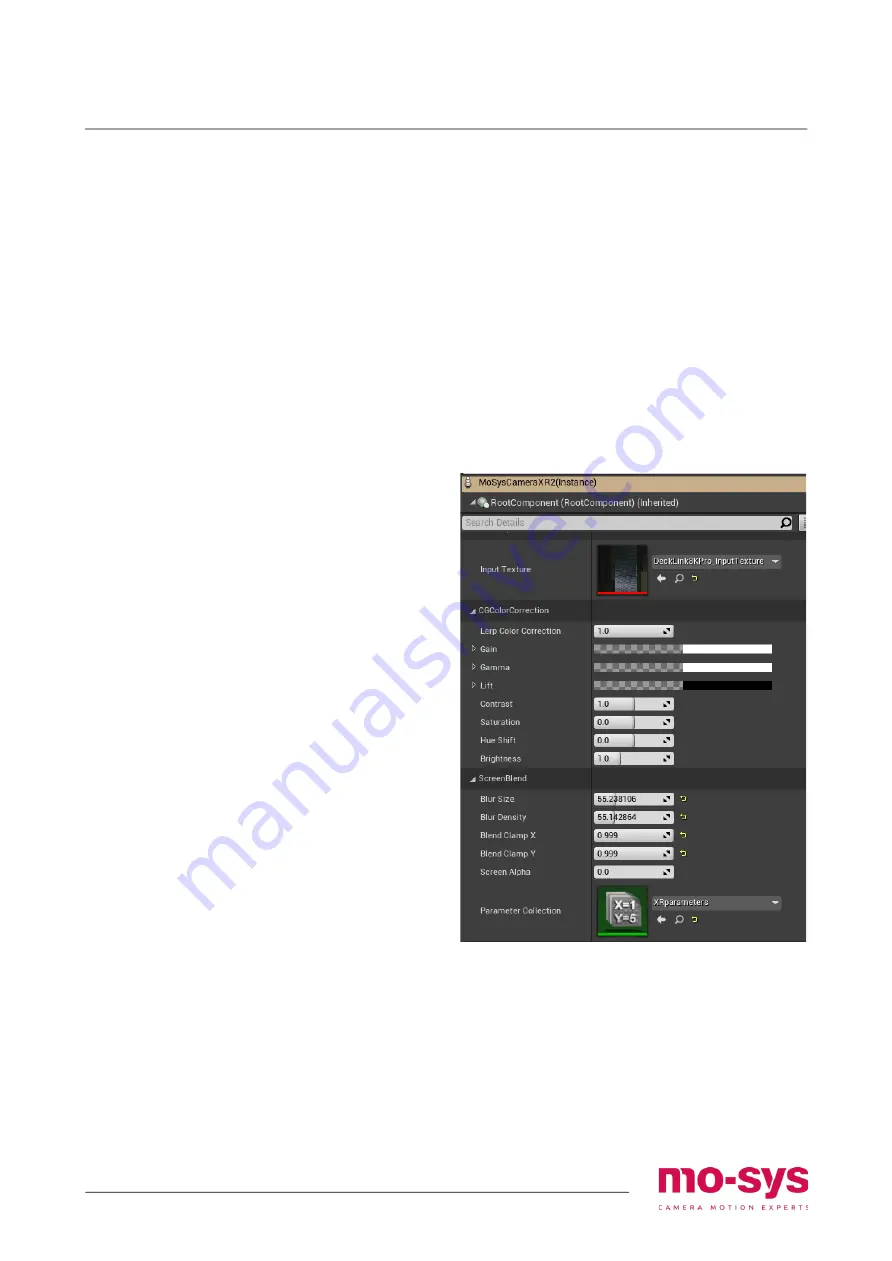
MoSysCameraXR
Apply the created livelink subject onto the
camera. In camera details select the input
texture to provide the video feed under
VideoInput -> Input Texture.
There are 2 sections of parameters on
MoSysCameraXR
that refer to the set
extension:
1. CGColorCorrection, which adjusts the
color of the CG graphics in the set
extension only to fit the video feed.
2. ScreenBlend, which provides tools of
blending the video with set extension
Test patterns
Test patterns are tools to verify the setup
geometry as well as colour correction. It is
crucial
to
provide
an
accurate
representation of the LED screens, so the
virtual objects are continuous through the
LED screen and the set extension. It is
equally important to make sure the colour is
matching on both.


