GV21001e_e_A5.doc / Jul-07
Page 10 / 11
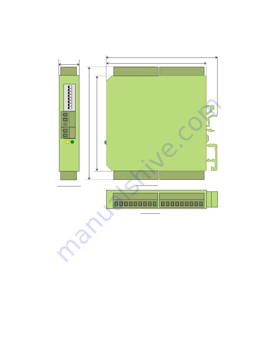
4.
Dimensions
102 (4.016”)
91 (3.583”)
8
2
.5
(
3
.2
4
”)
1
0
.0
6
22.5
(0.886”)
12345678
O
F
N
Side view
Top view
Front view
Page 1: ...A B B Z Z A A B B Z Z A A B B Z Z A A B B Z Z Universal encoder interface applicable as level converter encoder splitter and encoder cross switch Two encoder inputs A B Z and A B Z adjustable to eith...
Page 2: ...this unit is used with applications where failure or maloperation could cause damage to a machine or hazard to the operating staff it is indispensable to meet effective precautions in order to avoid s...
Page 3: ...1 Dual level converter 4 1 2 Encoder splitter dual output 4 1 3 Encoder signal switcher 5 2 Connection Diagram 6 2 1 Power supply 6 2 2 Control inputs 6 2 3 Encoder inputs 6 2 4 Outputs 7 3 The Front...
Page 4: ...put 1 LOW or unconnected and Control input 2 HIGH the signal ways are as shown in the drawing above featuring two independent level converters 1 2 Encoder splitter dual output In1 Control 1 LOW n c Co...
Page 5: ...ven when no inverted signals are applied to the input Inputs Control1 and Control2 select the signal ways LOW The corresponding output is connected to input 1 HIGH The corresponding output is connecte...
Page 6: ...2 position power terminal on the front side terminal 1 terminal 2 GND The current consumption is about 50 mA aux voltages and outputs unloaded 1 5 Control inputs The control inputs are accessible via...
Page 7: ...the switching threshold lies between 6 5 and 8 volts The input uses an internal pull down resistor of 5kOhms Every of the two input terminals provides two auxiliary voltage outputs for easy encoder su...
Page 8: ...nd the basic function of the unit Yellow LED off Control1 and Control2 are either both LOW or both HIGH at the same time In this case the unit operates as a splitter both outputs are connected to the...
Page 9: ...volts 0 Z 0 B 0 A Input 2 differential A A B B Z Z Both input and inverted input must be available Levels from 2 to 30 volts are acceptable 1 Z 1 B 1 A Input 2 single ended A B Z with HTL level Invert...
Page 10: ...GV21001e_e_A5 doc Jul 07 Page 10 11 4 Dimensions 102 4 016 91 3 583 82 5 3 248 102 4 016 22 5 0 886 1 2 3 4 5 6 7 8 OFF ON Side view Top view Front view...
Page 11: ...Max frequency 400 kHz RS422 200 kHz HTL Inputs Single ended A B Z 2x 10 30 volts or differential A A B B Z Z 2x 2 30 volts Outputs Push pull A A B B Z Z 2x Level 5 30 volts 30 mA short circuit proof...