Series 937B Vacuum System Controller
Operation and Maintenance Manual
Instruction Manual p/n: 100016467
Rev F, August 2020
Page 1: ...Series 937B Vacuum System Controller Operation and Maintenance Manual Instruction Manual p n 100016467 Rev F August 2020...
Page 2: ...using Front Panel Control Button 42 6 6 2 Power including degas Control of a Sensor via 37 pin AIO D sub Connector 43 6 6 3 Power including degas Control of a Sensor using Serial Communication Command...
Page 3: ...nd Installing AIO Module 87 10 3 Removing and Installing Profibus Control Module 88 10 4 Mounting the Controller 89 10 5 AC Power Cord 90 11 Maintenance and Service of MKS Vacuum Sensors 91 11 1 422 4...
Page 4: ...ll advise you if the hazardous materials document is required When returning products to MKS be sure to package the products to prevent shipping damage Shipping damage on returned products due to inad...
Page 5: ...erly Ground the Controller This product is grounded through the grounding conductor of the power cord To avoid electrical shock plug the power cord into a properly wired receptacle before connecting i...
Page 6: ...voltages when on High voltage is present in the cable and a Cold Cathode sensor when the Controller is turned on Use the proper power source This product is intended to operate from a power source th...
Page 7: ...2 to 100 of the measurement range of the head e g 1 Torr head is 2 0 x 10 3 to 1 0 x 10 0 Torr Allowed range within which a control sensor may switch on a Cold or Hot Cathode Pirani 5 0 x 10 4 to 9 5...
Page 8: ...p for each channel up to two 2 wide range combination logarithmic outputs Output impedance 100 ohms Number of channels Up to 6 Front panel controls Power ON OFF switch keypad for setup and operationa...
Page 9: ...and the total current requirement of operating sensor s must be 1 amp or less Pressure measurement ranges CC Cold Cathode 1 0 x 10 11 to 1 0 x 10 2 Torr 1 3 x 10 11 to 1 3 x 10 2 mbar 1 3 x 10 9 to 1...
Page 10: ...at constant temperature CM 0 25 of indicated pressure at constant temperature Calibration gas CC HC Nitrogen Argon Pirani CP Air nitrogen Argon Helium CM Any gas independent Installation orientation C...
Page 11: ...HC Pirani 0 to 50 C 32 to 122 F CP 10 to 50 C 50 to 122 F CM 0 to 50 C 32 to 122 F Maximum sensor bakeout temperature without cables CC Series 431 250 C 482 F when backshell subassembly removed otherw...
Page 12: ...i BA 3x10 10 Torr Dimensions CC Series 431 and 422 2 2 6 3 in 56 160 mm Series 423 2 6 3 4 in 66 86 mm Mini BA 1 12X2 37 in 28 60 mm with 2 3 4 CF flange LPN 3 3X1 0 in 83 mm 25 with 2 3 4 CF flange c...
Page 13: ...Power is OFF to HC CC CP PR sensor WAIT CC and HC startup delay Low EMIS The HC OFF due to low emission current CTRL OFF The HC or CC are turned OFF by the control channel or sensor PROT OFF The HC or...
Page 14: ...button Pressure Range Convection Pirani Pirani Hot Cathode Cold Cathode Torr PatchZ Default HighR PatchZ Default HighR PatchZ Default HighR PatchZ Default HighR 103 X X0E 03 X XE 03 ATM ATM 102 X X0E...
Page 15: ...cation Response Format CM and Piezo Diff Baratron Pirani Convection Hot Cathode Cold Cathode X XXXE X X XXXE X X XXE XX X XXE XX X XXE XX X XXE XX X XXE X Table 2 3 937B Serial Communication Response...
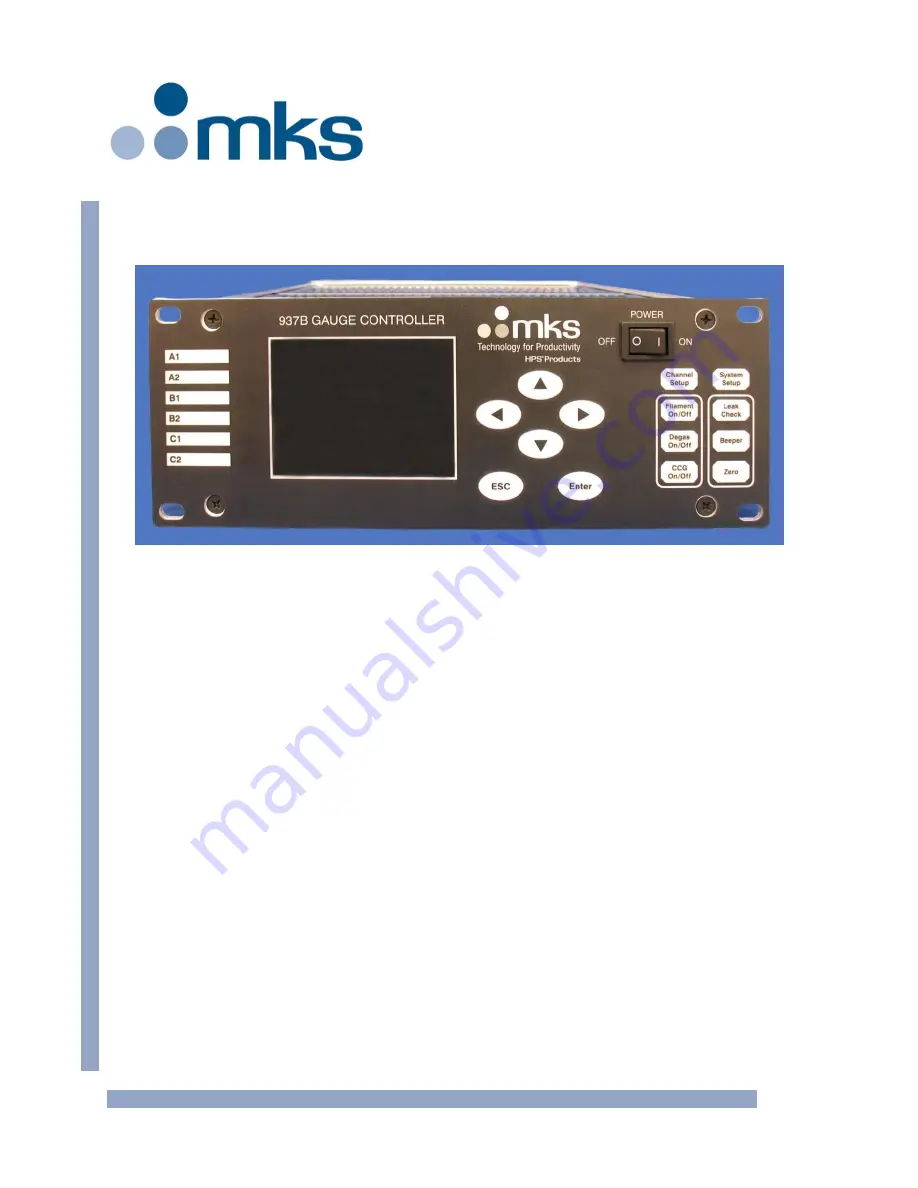
Page 16: ...937B Controller Instruction Manual pg 16 3 Feature Control Locations and Dimensions Figure 3 1 937B Front Panel Figure 3 2 937B Rear Panel Example...
Page 17: ...ndicating Active Channel 3 Liquid Crystal Display 4 Push Buttons for Menu Navigation 5 Power Switch 6 AIO Module 7 AC Power Inlet 8 RS232 485 Communication Port 9 Relay Output Port 10 Analog Output Po...
Page 18: ...ormal pressure situations and initiating appropriate security measures using the relay set points Controlling system pressure by using the analog output as the input to an automatic pressure controlle...
Page 19: ...sor combinations the Series 937B Vacuum System Controller can accommodate many unique requirements and applications It is designed with versatility and ease of use in mind with a large LCD screen that...
Page 20: ...e is a longer time delay 100 msec due to the signal processing by the microprocessor There are also combined logarithmic analog outputs available By combining the sensors with different measurement ra...
Page 21: ...ht arrow keys to lock or unlock the front panel controls or to display the lock status The front panel can also be locked or unlocked with serial communications commands See RS232 RS485 Communications...
Page 22: ...play of a single channel is also available to ensure the pressure readings can be seen at a distance To enter this mode 1 While in the standard display mode press the UP or DOWN arrow key to select th...
Page 23: ...for the controller and modules In addition the logarithmic linear analog output for individual channels and combined logarithmic analog output can be scaled by setting the DAC parameters Figure 6 3 93...
Page 24: ...UP or DOWN arrow key to change the parameter value i e to change Pascal to mBar 4 Pressing the ENTER key at this point will restore the original parameter If the cursor is moved away from the paramet...
Page 25: ...asting only 4 Baud Rate This sets the baud rate for serial communication Valid values are 9600 19200 38400 57600 115200 The default value is 9600 5 Command Mode This allows the use of either 937B or o...
Page 26: ...usting the DAC parameter To view or modify the DAC parameter press SYSTEM SETUP and move the cursor to Set DAC Parameter Select Edit and press ENTER The DAC parameters used in scaling the logarithmic...
Page 27: ...0V linear output is needed at a pressure different from that given above it can be entered via serial communication using the DLAn and DLT commands outlined in Section 9 14 14 FV firmware version Info...
Page 28: ...d control channel selection are accomplished using Channel Setup Figure 6 7 shows the channel setup parameters for all of the sensors and devices operated by the 937B controller The default values are...
Page 29: ...937B Controller Instruction Manual pg 29 Figure 6 7 937B Channel Setup Setting Parameters their Default Values and Ranges...
Page 30: ...lect the correct voltage Press ENTER to save the setting either 10 or 5 V 3 Range The full scale pressure range of the capacitance manometer needs to be set Capacitance manometers with full scale rang...
Page 31: ...r Autozeroing Capacitance Manometers The Capacitance Manometer and the reference auto zero sensor must be connected to the same chamber at all times 6 Manual Zero This allows for manual zeroing of the...
Page 32: ...t to 0 9xSet point if DIR is set to BELOW the hysteresis is automatically set to 1 1xSet point To modify the hysteresis move the cursor to the hysteresis value and press ENTER Use the UP or DOWN arrow...
Page 33: ...l NO Sensor Figure 6 9 Pirani Convention Pirani Setup Information Screen 1 Sensor The Sensor Type Convection Pirani or Pirani is often auto detected during the initial power up If the sensor type is a...
Page 34: ...is over 1x10 2 Torr 6 ATM Value The entered value is used for the atmospheric reading of the Pirani CP when an ATM Cal is performed The default value is 760 Torr Recall that elevation and weather will...
Page 35: ...PR CP gauges is 0 9xSet point when DIR is set to ABOVE the minimum hysteresis is 1 1xSet point when DIR is set to BELOW 13 Power Control of a Convection Pirani or Pirani Sensor Pirani or Convection P...
Page 36: ...until the delay has expired The delay can be adjusted from 3 to 300 seconds and the default value is 3 seconds When the AO delay is active WAIT will be displayed on the front panel rather than a pres...
Page 37: ...to stay in the activated closed state regardless of pressure and set point values CLEAR forces the relay to stay in the deactivated open state regardless of pressure and set point values ENABLE the re...
Page 38: ...t locations For example when the PR CP CM is installed on the foreline between the mechanical and turbo pumps monitoring the mechanical pump pressure and the CC is installed on the high vacuum chamber...
Page 39: ...ay 01 SET Dir Ch SET SP BELOW Hyst Enable 1 0E 06 9 0E 07 BELOW CLEAR 3 0E 05 3 3E 05 Relay 04 Relay 03 BELOW ENABLE 2 0E 08 1 8E 09 BELOW CLEAR 5 0E 07 5 5E 07 Filament 1 30 EC 20 uA DG Time Sensitiv...
Page 40: ...orr and automatically switched to 1 mA when pressure is below 1x10 4 Torr 6 Protect SP The Protect Set Point is turns off the hot cathode operating voltages based on its own pressure readings The Prot...
Page 41: ...thode from operating at high pressure extending the service life The adjustable Control SP range depends upon the sensor used for control 2x10 3 to 1x10 2 Torr for a Convection Pirani or Convectron 5x...
Page 42: ...int before using the front panel key to switch the sensor 3 The Sensor ON OFF key switches the corresponding sensor ON and OFF When a Hot Cathode is turned ON the filament power may turn OFF automatic...
Page 43: ...or removing ground from the pin turns the gauge power back ON Sensor power is turned ON when a rising edge is detected Any of the three turn ON OFF methods can be over ridden by the other For instance...
Page 44: ...itance manometer which is not gas dependent The leak test mode and bar graph will not be displayed if the 937B Controller detects that the requested sensor for leak testing is a capacitance manometer...
Page 45: ...lecular weight and that of the system gas The type of vacuum pump used can also affect the accuracy of the leak test For moderate size leaks pump down the system with a high vacuum pump such as a diff...
Page 46: ...correct on automated gas delivery systems 7 2 Installing Cold Cathode Sensors Verify that the vacuum port to which the CC sensor is mounted is electrically grounded It is essential for personnel safet...
Page 47: ...conductive all metal clamp to ensure the sensor body is grounded If the I Mag Sensor has a CF flange remove the magnet first to allow clearance for bolt installation To remove the magnet undo the two...
Page 48: ...seal is not recommended for high vacuum as outgassing and or permeation through the elastomer can cause errors in pressure measurement A sensor with a KF flange and elastomer O ring seal is suitable...
Page 49: ...chamber or manifold pressure Install the sensor away from pumps and gas sources for the most representative data Place the sensor in a location with minimal vibration 7 4 2 Preventing Contamination in...
Page 50: ...can blow the sensor out of a compression fitting damaging equipment and possibly injuring personnel Do not use a compression mount quick connect to attach the sensor to a system in positive pressure...
Page 51: ...ment of operating sensor s must be 1 amp or less See an MKS Baratron instruction manual for complete information on using these capacitance manometers The Series 937B Controller also supports the gas...
Page 52: ...ub Connector on CM Module 7 6 Series 902B Piezo The Controller also supports the gas independent Series 902B Piezo resistive gauges The 9 pin versions can be operated off the Capacitance Manometer mod...
Page 53: ...ess a pressure signal results in a relay activation time delay of between 50 to 100 msec 8 1 1 Pin Out for the 937B Relay Output Table 8 1 identifies the pins for the 25 pin D connector on the AIO Pow...
Page 54: ...the measured pressure is lower than the set point For example using relay activation in the BELOW mode a normally closed isolation valve can be opened only when the pressure is below its set point Si...
Page 55: ...reduce relay contact life In these situations an arc suppression network shown schematically in Figure 8 2 is recommended Figure 8 2 Relay Arc Suppression Network The values of the capacitance C and...
Page 56: ...processing However the buffered output from a hot cathode sensor at pin 1 3 or 5 in the table 8 2 is a microprocessor formed output This is because the hot cathode sensor uses different emission curr...
Page 57: ...937B Controller Instruction Manual pg 57 Figure 8 3 Buffered Analog Output for Cold Cathode Sensors 431 422 423 in N2...
Page 58: ...8 1 0E 04 9 3297 4 0E 09 4 6807 1 5E 04 9 4255 6 0E 09 4 8991 2 0E 04 9 4826 8 0E 09 5 0452 3 0E 04 9 5605 1 0E 08 5 1579 4 0E 04 9 6076 1 5E 08 5 3563 6 0E 04 9 6708 2 0E 08 5 4924 8 0E 04 9 7034 3 0...
Page 59: ...937B Controller Instruction Manual pg 59 Figure 8 4 Buffered Analog Output for Hot Cathode Sensors...
Page 60: ...937B Controller Instruction Manual pg 60 Figure 8 5 Buffered Analog Output for a 345 Pirani Sensor...
Page 61: ...1 3751 1 6066 6 0E 02 1 9652 1 6162 1 9148 8 0E 02 2 2254 1 8213 2 1788 1 0E 01 2 4526 2 0015 2 4131 1 5E 01 2 9255 2 3794 2 9143 2 0E 01 3 3095 2 6885 3 3370 3 0E 01 3 9177 3 1815 4 0419 4 0E 01 4 3...
Page 62: ...V p 9 3 V V 9 72 V 20 p 1 103 Torr 8696 0 3 2 10 34 1 621 9 621 9 4123 V V p Argon 0 63 V 7 79 V 1 10 4 p 20 Torr 1 3961 0 63 63 663 1 2 V p 7 79 V V 8 05 V 30 p 1 103 Torr 729 0 4 2 10 464 5 9386 7...
Page 63: ...937B Controller Instruction Manual pg 63 Figure 8 6 Buffered Analog Output for the 317 Convection Pirani Sensor or 275 Convectron Sensor...
Page 64: ...02 1 2884 1 0782 1 1755 8 0E 02 1 4465 1 1985 1 3147 1 0E 01 1 5870 1 3066 1 4398 1 5E 01 1 8866 1 5399 1 7110 2 0E 01 2 1371 1 7370 1 9427 3 0E 01 2 5480 2 0637 2 3341 4 0E 01 2 8825 2 3318 2 6645 6...
Page 65: ...10 372 5 503 8 503 8 5 399 V V p p 300 Torr 9177 0 512 3 exp V p Argon 0 56 V 7 00 V 1 10 4 p 60 Torr 002 1 2 1 3205 0 083 51 6 3 V p 7 00 V V 7 4 V 60 p 300 Torr 3 2 10 789 3 042 7 042 7 2 411 V V p...
Page 66: ...Buffered Capacitance Manometer Analog Output Pressure Torr 10 4 10 3 10 2 10 1 100 101 102 103 104 Output Voltage V 0 01 0 1 1 10 0 1 Full Scale Range Torr 1 0 10 100 1000 10 000 Figure 8 7 Buffered...
Page 67: ...are available These can provide a wider pressure range coverage since the combination output combines the measurement ranges of multiple gauges When Capacitance Manometers are used in combination no s...
Page 68: ...t be assigned as the middle pressure range sensor Middle in Figure 8 8 When a Pirani or Convection Pirani is used in combination only HC CC can be assigned to the low pressure range sensor Only capaci...
Page 69: ...inear analog output when the sensor power is turned OFF or the combined analog output is disabled Analog Out Volts Linear Out volts Log Linear Out Volts 937B Power OFF 0 0 0 CP Convectron channel OFF...
Page 70: ...in 9 3 to 9 14 Response Responses as described in 9 3 to 9 14 For example to query pressure on channel A1 use 003PR1 FF and the corresponding response is 003ACK7 602E 2 FF Here aaa 003 Command PR1 Re...
Page 71: ...FF or HC PR CP power is OFF RP_OFF HC and CC power is turned OFF from rear panel control WAIT CC or HC startup delay LowEmis HC OFF due to low emission CTRL_OFF CC or HC is OFF in controlled state PRO...
Page 72: ...the current setting value For CC and HC only BELOW can be selected NAK162 For CC and HC as the relay direction is fixed to BELOW ENm m 1 to 12 SET ENABLE or CLEAR SET ENABLE or CLEAR Query or set stat...
Page 73: ...ds 9 6 Convection Pirani Convectron and Pirani Control Commands Command Parameter Response Function ATMn n 1 to 6 d ddE ee ambient pressure d ddE ee Send an atmospheric pressure to perform ATM calibra...
Page 74: ...and 1 2 CSP to 0 03 Torr for Capacitance Manometer Default value is 1 5X the control set point value CSEn n 1 3 5 A1 B1 A2 B2 C1 C2 OFF A1 B1 A2 B2 C1 C2 OFF Query enable disable the control channel s...
Page 75: ...1 A2 B2 C1 C2 OFF Query enable disable the control channel status for an HC sensor on channel n CTLn n 1 3 5 AUTO SAFE OFF AUTO SAFE OFF AUTO HC CC can be turned ON OFF by the controlling sensor PR CP...
Page 76: ...Enable MT T1 T2 T3 T4 Display the sensor module type T1 T2 T3 CC HC CM PR FC NC NC no connection T4 NA PF for PROFIBUS PC STn n A B C S1S2 Display the connected sensor type on the specified module A B...
Page 77: ...C offset parameter B Default value is 7 2 Use n 0 for combination output Valid range is from 20 to 20 when DLT is set to LOG and always equals to zero when DLT is set to LIN IU ON or OFF ON or OFF For...
Page 78: ...DCATHODE 155 NOT_CAPACITANCE_MANOMETER 156 NOT_PIRANI_OR_CTP 157 NOT_PR_OR_CM 158 NOT_MFC 159 NOT_VLV 160 UNRECOGNIZED_MSG 161 SET_CMD_LOCK 162 RLY_DIR_FIX_FOR_ION 163 INVALID_CHANNEL 164 DIFF_CM 165...
Page 79: ...o Ch B1 AUTZ3 5 Autozero Ch B2 AUTZ4 6 Autozero Ch C1 AUTZ5 7 Autozero Ch C2 AUTZ6 8 Gas Type Ch A1 GT1 9 Nitrogen Argon Helium Custom HC only Local Setting Gas Type Ch A2 GT2 10 Gas Type Ch B1 GT3 11...
Page 80: ...B2 CTL4 39 Ctrl Enable Ch C1 CTL5 40 Ctrl Enable Ch C2 CTL6 41 Fast Relay Ctrl Ch A1 FRC1 42 1E 7 2E 7 4E 7 8E 7 1E 6 2E 6 4E 6 8E 6 1E 5 2E 5 4E 5 8E 5 1E 4 Local Setting Fast Relay Ctrl Ch B1 FRC3...
Page 81: ...Bit 3 Enable Clear Set point Relay 12 Bit 4 N A Bit 5 N A Bit 6 N A Bit 7 N A 2 1 Bit field Bit 0 Bit 1 Bit 2 Bit 3 Bit 4 Bit 5 Bit 6 Bit 7 Power CC HC PR Channel A1 Power CC HC PR Channel A2 Power C...
Page 82: ...Factory Default Channel B2 Factory Default Channel C1 Factory Default Channel C2 N A N A 8 4 Float Relay Set point Pressure for Relay 1 12 4 Float Relay Set point Pressure for Relay 2 Flow Set point f...
Page 83: ...6 24 1 Byte Status for Channel 1 1 NOGAUGE 2 NEGATIVE 3 CONTROL 4 HI 5 LO 6 OFF 7 AA 8 PROTECT 9 WAIT 10 RP_OFF 11 Degas 12 FAULT 13 OPEN for MFC only 14 CLOSE for MFC only 15 SET POINT for MFC only 1...
Page 84: ...NEGATIVE 3 CONTROL 4 HI 5 LO 6 OFF 7 AA 8 PROTECT 9 WAIT 10 RP_OFF 11 Degas 12 FAULT 13 OPEN for MFC only 14 CLOSE for MFC only 15 SET POINT for MFC only 16 PID for MFC only 28 1 Byte Status for Chan...
Page 85: ...nt Relay State Relay 9 1 Set point Relay State Relay 10 2 Set point Relay State Relay 11 3 Set point Relay State Relay 12 4 N A 5 N A 6 N A 7 N A 32 4 Float Set point Relay State Relay 1 36 4 Float Se...
Page 86: ...module in the slot Typically 937B Controllers are shipped with customer specified sensor modules To change the controller configuration by removing and installing modules follow the steps shown below...
Page 87: ...hat the controller power is OFF and the power cord is disconnected 2 Use a 1 Phillips screwdriver to remove the four 4 screws on the four corners of the rear panel of the AIO module 3 Place a small fl...
Page 88: ...ips screwdriver to install and tighten the four 4 screws on the four corners of the rear panel of the module 10 3 Removing and Installing Profibus Control Module In the 937B Controller the slot labele...
Page 89: ...n D Sub communications connector is located on the back panel of the AIO Power module 10 4 Mounting the Controller The 937B Controller was designed for both rack mounting and bench top use In both cas...
Page 90: ...ions to other mounting configurations 10 5 AC Power Cord The Controller has a standard female IEC 60320 connector for connecting to a 100 240 VAC 50 60 Hz power source Use only a harmonized detachable...
Page 91: ...current or filament voltage is needed Degassing is not needed Sensor tubes can often be cleaned and reused almost indefinitely The control circuit is simple and reliable having only one current loop a...
Page 92: ...l cylindrical magnet which provides an axial field The cathode is isolated from the grounded metal housing The inverted magnetron geometry produces more stable signal output and also works well to low...
Page 93: ...ocket head cap screws 10 and pull the back flange 13 free Note that these screws are silver plated for lubricity and should be used only once They may be re lubricated with a dry lubricant such as mol...
Page 94: ...or chemically Do not touch any vacuum exposed part after cleaning unless wearing gloves Ultrasonic cleaning should use only high quality detergents compatible with aluminum e g ALCONOX Scrub surfaces...
Page 95: ...ting a Cold Cathode Sensor MKS cold cathode sensors contain anode and cathode collector electrodes Test the sensor with an ohmmeter There should be no shorts between the electrodes or from the electro...
Page 96: ...ng 1 on the ion current feed through pin when assembling or disassembling the sensor Leaf Spring High Voltage Feedthrough Pin Flathead Screw 2 Magnet Ion Current Feedthrough Pin Glass Insulator Locati...
Page 97: ...hods described above should be followed with multiple rinses of deionized water Dry all internal components and the sensor body 9 in a clean oven set at 150 C The two ceramic spacers 4 and 7 are sligh...
Page 98: ...he ion numbers are in proportion to the ambient gas pressure Electrons are accelerated through the structure by a potential difference between the hot emitting filament and a positively charged surrou...
Page 99: ...an remove surface contamination on the grid and collector Severe contamination of the grid structure may require a replacement of the sensor Although the feed through insulators are shielded in some a...
Page 100: ...maintained at a constant temperature during the measurement process Figure 11 7 Schematic of a Pirani Thermal Conductivity Sensor The amount of heat exchanged between the hot wire and a colder enviro...
Page 101: ...1000 Torr 11 5 1 Cleaning the Series 345 Sensor Roughing pump oils and other fluids condensing or decomposing on the heated filament can contaminate the sensor This changes the emissivity of the filam...
Page 102: ...or electronics subassembly from the end of the sensor 2 Check the resistance on the sensor s pins listed in the first column in Table 11 3 Test the sensor using an ohmmeter with less than 5 mA of curr...
Page 103: ...is to be measured The other reference side contains an electrode assembly placed in a reference cavity see Figure 11 9 Absolute transducers have the reference side factory sealed under high vacuum 10...
Page 104: ...essure control 100016609 Cable for Capacitance Manometer Type 722B 10 ft 3 0 m 100016951 25 ft 7 6 m 100016952 50 ft 15 2 m 100016953 Cable for Capacitance Manometer Type 626B 627D 10 ft 3 0 m 1000075...
Page 105: ...ection Pirani 345 Pirani Sensor 10 ft 3 0 m 103170006SH 25 ft 7 6 m 103170007SH 50 ft 15 2 m 103170008SH 100 ft 30 5 m 103170017SH Custom to 500 ft 152 4 m 103170009SH Cable for 275 Convectron Sensor...
Page 106: ...937B Controller Instruction Manual pg 106 Series 937B Vacuum System Controller Operation and Maintenance Manual Instruction Manual p n 100016467 Rev F August 2020...