background image

9

WARNING

In order to prevent electrical shock and injury, the following electrical safety precautions and symbols 

should be followed at all times!

If permanently connected this tool should be connected to a grounded metal permanent 

wiring system; or to a system having an equipment - grounding conductor.

In case of a malfunction or breakdown, grounding provides a path of least resistance for electrical 

current to reduce the risk of electric shock. This tool is equipped with an electric cord which has an 

equipment-grounding conductor and a grounding plug. The plug must be plugged into a matching 

outlet that is properly installed and grounded in accordance with all local codes and ordinances.

•   DO NOT modify the plug provided - if it will not fit the outlet, have the proper outlet 

  installed by a qualified electrician.

•   Improper connections of the equipment-grounding conductor can result in a risk of electric  

  shock. The equipment-grounding conductor is the insulated conductor that has an outer  

  surface that is green, with or without yellow stripes. If repair or replacement of the electric  

  cord or plug is necessary, DO NOT connect the equipment-grounding conductor to a live  

 terminal.

•   Check with a qualified electrician or service personnel if the grounding instructions are not  

  completely understood, or if in doubt as to whether the tool is properly grounded.

•   Use only 3-wire extension cords that have 3-prong grounding plugs and 3-pole receptacles  

  that accept the tool’s plug.

•   Repair or replace a damaged or worn cord immediately.

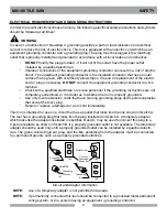
This tool is intended for use on a circuit that has an outlet that looks like the one shown in Sketch A. 

The tool has a grounding plug that looks like the plug illustrated in Sketch A. A temporary adapter, 

which looks like the adapter illustrated in sketches B and C, may be used to connect this plug to a 

2-pole receptacle as shown in Sketch B, if a properly grounded outlet is not available. The temporary 

adapter should be used only until a properly grounded outlet can be installed by a qualified electri-

cian. The green-colored rigid ear, plug, and the like, extending from the adapter, must be connected 

to a permanent ground, such as a properly grounded outlet box.

ELECTRICAL REQUIREMENTS AND GROUNDING INSTRUCTIONS

NOTE:  

ON

(

(

)

)

Grounding

Means

(A)

Metal Screw

Cover of 

Grounded

Outlet Box

(D)

ADAPTER

(C)

Grounding

Pin

Grounding

Pin

(B)

Circuit and Adapter Information

Use of a temporary adapter is not permitted in Canada.

NOTE: 

MK-100 TILE SAW                                                                                         SAFETY    

Summary of Contents for MK-100

Page 1: ...S MANUAL PARTS LIST OPERATING INSTRUCTIONS www mkdiamond com Caution Read all safety and operating instructions before using this equipment This parts list MUST accompany the equipment at all times Re...

Page 2: ...e and maintain your MK 100 Tile Saw safely and correctly Please take the time to familiarize yourself with the MK 100 Tile Saw by reading and reviewing this manual Read and follow all safety operating...

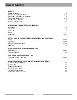
Page 3: ...Stand 17 Assembly 18 19 SETUP STARTUP ADJUSTMENT OPERATION and SHUTDOWN Setup 20 22 Operation 23 26 Cutting Head Adjustment 27 28 Cleanup 29 MAINTENANCE AND TROUBLESHOOTING Maintenance 30 35 Troublesh...

Page 4: ...t symbol and one of three words DANGER WARNING or CAUTION DANGER You WILL be KILLED or SERIOUSLY INJURED if you do not follow directions WARNING You CAN be KILLED or SERIOUSLY INJURED if you do not fo...

Page 5: ...r dust removal Use dust collection system when applicable NEVER operate the machine in an explosive atmosphere or near combustible materials Sparks from the cutting action of this machine can ignite f...

Page 6: ...dangerous or hazardous environments DO NOT use power tools in damp or wet locations nor expose them to rain Always keep the work area well lighted REMOVE ADJUSTING KEYS AND WRENCHES KEEP WORK AREA CLE...

Page 7: ...EVER disconnect any emergency or safety devices These devices are intended for operator safety Disconnection of these devices can cause severe injury bodily harm or even death Disconnection of any of...

Page 8: ...filter out microscopic particles Where use of a dust extraction device is possible it should be used To achieve a high level of dust collection use an industrial HEPA vacuum cleaner Observe OSHA 29 C...

Page 9: ...equipment grounding conductor to a live terminal Check with a qualified electrician or service personnel if the grounding instructions are not completely understood or if in doubt as to whether the to...

Page 10: ...the electric motor refer to your electric motor instruction book let furnished with the electric motor Protect the electric motor from dust as much as possible and keep ventilating openings clean Bef...

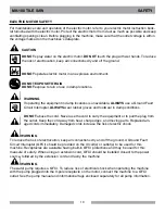
Page 11: ...eptacle Supporting Surface Power Tool Drip Loop Power Cord Drip Loop Information WARNING ON WARNING Use only extension cords that are intended for outdoor use These extension cords are identified by a...

Page 12: ...t in motor burnout and premature failure MK Diamond warns that equipment returned to us showing signs of being run in a low voltage condition through the use of undersized extension cords will be repa...

Page 13: ...el I Label B Label A Label C SERVICE OR WARRANTY FOR INFORMATION ON PLEASE CALL 1 800 474 5594 WARNING Grinding cutting drilling of masonry concrete metal and other materials with silica in their comp...

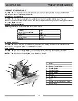
Page 14: ...y 20 inches in length depth of cut 3 Motor specifications for the MK 100 are listed in below Voltage 120V Motor Only Amperage 14 5 Frequency 60Hz RPM 3400 rpm Horse Power 1 5 hp Weight 96 lbs The MK 1...

Page 15: ...Inc P N 155037 MK Warranty Card 02 10 mK diamoNd warraNty 1315 Storm Parkway Torrance CA 90509 USA www mkdiamond com 1 800 421 5830 1 310 539 5158 where did you purChase this saw From Name CommeNts o...

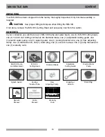
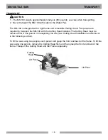
Page 16: ...Installation and Removal in the following section To lift the saw using two people each person will grasp the front and back of the frame To lift the saw using one person remove the Cutting Head first...

Page 17: ...ction when placing it on the stand MK Diamond Part 168244 If using the Optional MK Diamond Stand follow these steps FOLDING STAND CAUTION A Open the stand and place on flat surface Remove Water Basin...

Page 18: ...DO NOT over tighten the nut A Position Movable Cutting Table to the front of the saw and raise the Blade Guard B Locate the Shaft Lock but ton on the underside of the Cutting Head C Depress and hold t...

Page 19: ...utting Guide onto the Movable Cutting Table Ruler Stop and tighten the retaining thumbscrew SPLASH GUARD INSTALLATION A Install the retaining thumbscrew through the washer and Splash Guard then align...

Page 20: ...ify the Movable Cutting Table moves freely C Inspect the Diamond Blade for damage Verify the blade is cor rect for the material being cut PRE START INSPECTION D Inspect the Pump Assembly for damage En...

Page 21: ...MK Diamond qualified replacement parts WARNING To prevent pump damage the Water Pump must be disconnected from its power supply if cutting with a Dry Blade WATER PUMP SETUP FOR OPERATION The Water Pum...

Page 22: ...should be used Voltage 120v Cycle 60Hz Phase 1 phase If using an extension power cord make sure the length and wire gauge correspond to he requirements listed in the Table on Page 10 An extension powe...

Page 23: ...A Ensure the ON OFF Switch is in the OFF position B Plug MK 100 into GFCI C Plug the GFCI into the power source Set Cutting Depth When loosening the Cutting Head Adjusting Knob the Cutting Head will...

Page 24: ...CAUTION A Position the Dual 45 Flat Angle Guide and tighten the retaining thumbscrew B Position the tile against the Dual 45 Flat Angle Guide and the Ruler Stop Turn on the motor C Verify proper cool...

Page 25: ...he 45 Bullnose Miter Guide should be used MK Diamond Part 134585 MK CAUTION NOTE A Position the 45 Bullnose Miter Guide and tighten the retaining thumbscrews B Position the tile on the 45 Bullnose Mit...

Page 26: ...desired angle and tighten the thumbscrew C Position the tile against the 90 Protractor and the Ruler Stop Turn the motor ON D Verify proper cooling flow on both sides of the blade See Mainte nance Sec...

Page 27: ...changing the position of the Cutting Head CAUTION A Remove the blade Support the Cutting Head and then remove Adjusting Knob B Remove the Cutting Head from the rear pivot hole E Install the Adjusting...

Page 28: ...ove Adjusting Knob B Remove the Cutting Head Cutting Head Adjustment pg 25 C Loosen the Retaining Bolts D Remove both the Standoffs and Retaining Bolts E Relocate the Post to the rear Post retaining h...

Page 29: ...and Local laws A Clean the Water Pump suction of all debris NOTE B Place the Water Pump in an external container MK 100 CLEANUP C Run the MK 100 until clear water is seen at the blade cooling ports A...

Page 30: ...h as 3 in 1 WD 40 etc Maintenance Following Use A Lubricate the Guide Bar B Lubricate the Roller Wheel Assembly The following maintenance should be performed monthly Monthly Maintenance A Remove the D...

Page 31: ...the threads on the Cutting Head Adjustment Knob J Lubricate the Cutting Head Adjustment Knob retaining holes K Lubricate the Cutting Head Pivot Shaft If flow to the diamond blade requires adjustment p...

Page 32: ...2 and by following the steps below Blade Dressing A Cut the Dressing Stick 7 or 8 times to dress the Blade When installing the Retaining Nut DO NOT cross thread and DO NOT over tighten the nut Diamond...

Page 33: ...irst forty eight 48 hours of operation NOTE A Remove the Diamond Blade B Remove the Cutting Head See Cutting Head Adjust ment Pg 25 C Remove the two top Belt Guard Bolts D Remove Belt Guard bottom bol...

Page 34: ...new V Belt MK Diamond Part No 158194 M Verify the V Belt is seated in the grooves of both pulleys N Tighten the Motor Adjustment Strap to remove slack O Check V Belt tension proper tension 1 8 inch R...

Page 35: ...See Pump Manual F Remove the Blade Guard Intake Fitting and check Rodding cooling channels is performed by inserting a small wire rod through the cooling inlet on top of the Blade Guard and directing...

Page 36: ...ound Fault Circuit Interrupter Verify circuit breaker at least 20 amps if not move to 20 amp circuit Verify circuit breaker not tripped If tripped reset once Check power source voltage is 120V if not...

Page 37: ...37 NOTES...

Page 38: ...38 1 2 3 4 5 6 7 8 9 11 12 13 14 26 19 20 21 22 23 25 16 17 18 24 10 27 15 MK 100 Exploded view MK 100 Tile Saw Part 158189...

Page 39: ...1 12 CLAMP HOSE 1 4 1 2 FLOW 154394 1 13 SCREW HEX HD 1 4 20X1 1 4 157145 1 14 STOP CUTTING HEAD 157728 1 15 ASSY CUTTING HEAD 100 158225 1 16 DRAIN PLUG W RING 159529 1 17 STRAP 9 DRAIN PLUG 159530 1...

Page 40: ...40 MK 100 Exploded view 1 2 3 4 5 6 7 8 9 13 INCLUDED WITH ITEM 8 2 3 5 10 12 MK 100 Cutting Head Part 158225...

Page 41: ...152582 1 5 WASHER LOCK SPLIT 1 4 152591 4 6 SCREW HEX HD TAP 1 4 20X1 152676 1 7 SCREW 5 16 18 X 3 8 SOCKET HEAD SET 157083 1 8 ASSY SUB CTTG HD 101 158191 1 9 BELT 6J260 158194 1 10 PULLEY 6J19 X 5...

Page 42: ...Description Part Qty 1 bar guide plated MK 101 134759 1 2 screw hex hd 5 16 18x1 151743 2 3 washer lock split 5 16 151747 2 4 WASHER FLAT SAE 5 16 151754 2 5 ASSY WHEEL BRKT TSAW 151756 1 6 casting t...

Page 43: ...VOT 153254 1 3 SCREW SET SOC CUPT 3 8 16X1 2 153710 1 4 PLATE PRESSURE 155671 1 5 SCREW 3 8 16 X 2 1 2 HEX HEAD CAP 156030 2 6 CASTING POST DC 101 MKRED COMP 158438 1 7 POST COVER PLASTIC 160157 1 8 S...

Page 44: ...BARB 90 DEG 154652 1 3 TUBE WATER 155389 2 4 CASTING 101 BLD GUARD DC COMP 162481 1 Item Description Part Qty 1 WHEEL ROLLER 151799 1 2 NUT HEX 1 4 20 151893 1 3 SCREW HEX HEAD 1 4 20 X 1 12 151914 1...

Page 45: ...WASHER LOCK SPLIT 5 16 151747 4 10 WASHER FLAT SAE 5 16 151754 5 11 STRAP 1 INCH MOTOR ADJ 152673 1 12 BUMPER RUBBER 1 2 DIA 152674 1 13 BOLT 3 8 16 X 3 1 2 HEX HEAD TAP 153147 1 14 SCREW 5 16 18 X 3...

Page 46: ...and the wet cutting machine to be used During cutting operations liberal amounts of water act as a coolant to support the cutting effectiveness and longevity of the WET blade Additionally using water...

Page 47: ...Dressing Stone Ground Fault Circuit Interrupter 5 6 7 8 9 10 Folding Stand Folding Stand with Casters 137166 Premium grade Diamond Blade for smooth chip free cutting on tile 128074 Supreme grade diam...

Page 48: ...elve 12 months Have the Model Number of the saw Have the Serial Number of the saw Have the location of where the saw was purchased Have the date when the saw was purchased Contact Customer Service for...

Page 49: ...ct at the time of approval for printing MK DIAMOND PRODUCTS INC will guarantee every machine they build to be free from defects in material and workmanship for 1 one year from date of purchase The obl...

Page 50: ...50 NOTES...

Page 51: ...51 NOTES...

Page 52: ...MK Diamond Products Inc 1315 Storm Parkway Torrance CA 90501 Toll Free 800 421 5830 Phone 310 539 5221 Fax 310 539 5158 www mkdiamond com MK 100 TILE SAW OWNER S MANUAL OPERATING INSTRUCTIONS...

Reviews: