background image

18

THIRD ANGLE PROJECTION

1

2

3

4

5

5

4

3

1

Folder

S:\Solidworks\Solidworks_Elo\Finish Mower\EURO Finishing Mower\60 Finishing Mower\60 Rear Discharge\53285.SLDASM

DWG. NO.

REV

Model

SCALE  1:12

SHEET 1 OF1

DATE DRAWN

MATERIAL

Rear deflector

November-23-16 5:56:02 PM

DESCRIPTION

Finishing Mower 60 rear

\\DC1\ENGINEERING\SOLIDWORKS\SOLIDWORKS_ELO\FINISH MOWER\EURO FINISHING MOWER\60 FINISHING MOWER\60 REAR DISCHARGE\

 Weight(lbs.)

0

Width

Height

Length

0

0

17.14

0

Blank Size

Unit of Measure

ITEM ID.

53285

Config ID

53285

DIMENSIONS ARE IN INCHES

TOLERANCES NON SPECIFIED:

FRACTIONAL   1/64 

BEND   1.0

TWO PLACE DECIMAL      0.01"

THREE PLACE DECIMAL   0.002"

Notes

DO NOT SCALE DRAWING

Item #

Part #

Description

Qty 48

Qty 60 Qty 72

1

53545

48  Rear deflector

1

53539

60  Rear deflector

1

53560

72  Rear deflector

1

2

53546

48  Holder cable

1

53538

60  Holder cable

1

53561

72  Holder cable

1

3

OL

3/16 Cable clamp

2

2

2

4

53081

Chain

37

47

55

5

OL

Bolt 3/8 x 1 c/w lw,n

4

4

4

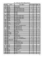
48 - 72 Pulsar Finish Mower Rear Shield

Item #

Part #

Description

Qty

44

53239

Top Link

1

45

53557

A Frame Brace Bar

2

46

OL

Bolt 5/8 x 6 c/w ln

1

47

53234

A Frame

2

48

53264

Stop Washer

2

49

OL

Bolt 3/4 x 2 1/4 c/w ln

2

50

mkfm900011

90 Inside spindle pulley

1

51

36167

Main Body Assembly

1

52

OL

Bolt 3/4 x 2 c/w ln

2

53

36519

Rear Shield

1

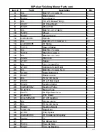
90 Pulsar Finishing Mower Parts cont.

Summary of Contents for Pulsar 48 rear

Page 1: ...ishing Mower 60 Rear Discharge 53285 SLDASM DWG NO REV Model SCALE 1 24 SHEET 3 OF5 DATE DRAWN MATERIAL 53285 May 17 16 10 54 20 AM DESCRIPTION Finishing Mower 60 rear S Solidworks Solidworks_Elo Finish Mower EURO Finishing Mower 60 Finishing Mower 60 Re Weight lbs 0 Width Height Length 0 0 422 75 0 Blank Size Unit of Measure ITEM ID 53285 Config ID 53285 DIMENSIONS ARE IN INCHES TOLERANCES NON SP...

Page 2: ......

Page 3: ...ration Safety Assembly Decal Location Operation Sign Off Form 48 72 Parts Deflector Parts Belt Arrangement Gearbox PTO Driveline Dimensions PTO Maintenance Bolt Torque Chart 2 3 4 5 6 7 8 9 10 11 12 14 16 16 17 17 18 19 20 21 22 23 24 ...

Page 4: ...t cover the following items 1 Normal replacement of service items 2 Normal maintenance or adjustments 3 Machines or parts lost or damaged during shipment 4 Accessory items parts not supplied by MK Martin 5 Damages resulting from misuse negligence accident theft or fire use of improper or insufficient fuel fluids or lubricants use of after market parts or accessories unless approved by MK Martin mo...

Page 5: ...ly assembled as directed by manufacturer Equipment was tested for functionality and operates properly Purchaser was instructed in safe and proper operating procedures Warranty was explained to purchaser Purchaser was given the operators manual Retailer Signature Company Address Purchaser s signature indicates Acceptance of equipment fully assembled Received operator s manual Clearly understands co...

Page 6: ...ge Stamp M K Martin Enterprise Inc 3950 Steffler Rd Elmira ON CA N3B 2Z3 Fold Here Please Cut and Return to M K Martin Enterprise Inc Fold And Tape here Do not tape all edges or use staples Warranty Registration ...

Page 7: ...anual Caution Indicates a potentially hazardous situation that may result in injury Warning Indicates a hazardous situation that could result in serious injury or death Danger Indicates a hazardous situation that needs to be avoided It is you the operator that needs to be aware of these dangers If you have any questions not answered in this manual please contact your dealer or M K Martin Enterpris...

Page 8: ...ng 10 Stay clear of the machine when engaging the PTO Keep others away 11 Clean reflectors SMV sign and lights if used before transporting 12 When transporting use hazard flashing lights 13 Do not put hands or feet under machine while tractor engine is running 14 Do not operate the mower in a raised position 15 Objects can be thrown out from the mower with sufficient force to severely injure peopl...

Page 9: ...is the right length and does not bind See page 22 for directions Assembly Information THIRD ANGLE PROJECTION 5 4 3 1 Folder idworks Solidworks_Elo Finish Mower EURO Finishing Mower 60 Finishing Mower 60 Rear Discharge 53285 SLDASM DWG NO R Model SCALE 1 24 SHEET 3 OF5 DATE DRAWN MATERIAL 53285 May 17 16 10 54 20 AM DESCRIPTION Finishing Mower 60 rear S Solidworks Solidworks_Elo Finish Mower EURO F...

Page 10: ...of Measure ITEM ID 53285 Config ID 53285 DIMENSIONS ARE IN INCHES TOLERANCES NON SPECIFIED FRACTIONAL 1 64 BEND 1 0 TWO PLACE DECIMAL 0 01 THREE PLACE DECIMAL 0 002 Notes DO NOT SCALE DRAWING 6 Part PULSAR x2 5 Part A75 x2 DANGER of possible shearing of limbs Keep a safe distance from the machine while it is working 1 Part 224 DANGER Sharp objects could be thrown Keep safe distance from the machin...

Page 11: ...and the machine 7 Part F9 Before operating ma chine carefully read the instruction manual Technical Data MOD Cut Width HP Blades RPM Weight Pulsar 48 side 48 14 20 3 540 350 Pulsar 48 rear 48 14 20 3 540 365 Pulsar 60 side 60 14 22 3 540 420 Pulsar 60 rear 60 14 22 3 540 425 Pulsar 72 rear 72 18 25 3 540 520 12 Part 220 DANGER of being caught by the PTO shaft Do not go near the rotating members of...

Page 12: ...til the deck is level Cutting height is controlled with spacers on the caster pivot Move spacers from top to bottom of wheel beam or bottom to top as needed for the proper cutting height Starting the Mower With the mower slightly raised from the ground wheels may be off the ground 3 6 inches Run the engine at a slow speed and slowly engage the PTO Slowly bring the engine to PTO speed Do not exceed...

Page 13: ...ged 4 Change gears to vary the ground speed For your safety do not travel faster then 4 MPH 6 km h It is the operator s responsibility to operate the machine in a safe manner at all times 5 If the grass is tall cut it twice to obtain the best results This allows the unit to cut less material on each pass 6 When mowing a new area for the first time you may want to set the deck height higher to clea...

Page 14: ...nyone else to operate this equipment until such information has been reviewed Annually review this information before the season start up Make these reviews of SAFETY and OPERATION annually as a standard practice for all your equipment We feel that an untrained op erator is unqualified to operate this machine A sign off sheet is provided for your record keeping to show that all personnel who will ...

Page 15: ...13 NOTES ...

Page 16: ...5 Config ID Exploded DIMENSIONS ARE IN INCHES TOLERANCES NON SPECIFIED FRACTIONAL 1 64 BEND 1 0 TWO PLACE DECIMAL 0 01 THREE PLACE DECIMAL 0 002 Notes DO NOT SCALE DRAWING 48 72 Pulsar Finish Mower Parts Item Part Description Qty 48 Qty 60 Qty 72 1 53537 Short spacer 8 8 8 2 53536 Long spacer 8 8 8 3 OL 3 16 Lynch pin 4 4 4 4 53245 Wheel fork 4 4 4 5 OL Bolt 1 2 x 4 1 2 c w ln 4 4 4 6 53337 Wheel ...

Page 17: ...drilling screw 2 2 2 31 53252 48 Right belt cover 1 53292 60 Right belt cover 1 53559 72 Right belt cover 1 32 OL Bolt 5 16 x 3 4 c w lw 2 2 2 33 53672 Slip clutch 1 1 1 34 DJA69351 PTO shield 1 1 1 35 F205J808 Gearbox 1 1 1 36 OL 5 8 Nut c w lw 4 4 4 37 53267 Gearbox slider 1 1 1 38 OL Bolt 3 8 x 1 c w lw fw n 10 10 10 39 OL Bolt 1 2 x 3 Full thread c w ln 1 1 1 40 NSMMZ29206 Adapter 3 3 3 41 OL ...

Page 18: ...2 53 OL Bolt 3 4 x 2 c w ln 2 2 2 54 21401 Spacer 2 2 2 55 53232 Hitch link 4 4 4 56 OL Bolt 3 4 x 2 1 4 c w ln 2 2 2 57 53061 Hitch pin c w lw n 2 2 2 58 53540 Short grease hose 2 2 1 59 53562 Long grease hose 1 1 2 60 OL Bolt 1 2 x 3 c w lw fw 4 4 4 61 53240 48 Wheel beam 2 53295 60 72 Wheel beam 2 2 62 53673 Bushing 4 4 4 90 Pulsar Finishing Mower Parts Item Part Descritption Qty 1 OL Bolt 3 8 ...

Page 19: ...2 c w ln 2 19 53232 Hitch Link 4 20 21401 Spacer 2 21 OL 1 8 x 1 Cotter Pin 3 22 21400 Complete Scalp Roller 3 23 OL Bolt 3 8 x 1 c w lw fw ln 6 24 21399 Scalp Roller Axle 3 25 53267 Roller bracket 3 26 OL 5 16 x 3 4 c w lw 2 27 36168 90 Left Belt Cover 1 28 53229 Gearbox Slider 1 29 mkfm900002 Gearbox Pulley 1 30 DJA70111 Manual Tube 1 31 36173 90 RIght Belt Cover 1 32 DJA69351 PTO Shield 1 33 cn...

Page 20: ...48 Holder cable 1 53538 60 Holder cable 1 53561 72 Holder cable 1 3 OL 3 16 Cable clamp 2 2 2 4 53081 Chain 37 47 55 5 OL Bolt 3 8 x 1 c w lw n 4 4 4 48 72 Pulsar Finish Mower Rear Shield Item Part Description Qty 44 53239 Top Link 1 45 53557 A Frame Brace Bar 2 46 OL Bolt 5 8 x 6 c w ln 1 47 53234 A Frame 2 48 53264 Stop Washer 2 49 OL Bolt 3 4 x 2 1 4 c w ln 2 50 mkfm900011 90 Inside spindle pul...

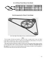
Page 21: ...isalignment Please do not tighten beyond this point Do not use any form of belt dressing as this causes the belts to become glazed or the dressing stays tacky and will collect dust and debris 48 60 Pulsar Finish Mower Side Shield Item Part Description Qty 48 Qty 60 1 53279 48 Side deflector 1 53303 60 Side deflector 1 2 OL Bolt 3 8 x 3 4 c w ln 2 2 THIRD ANGLE PROJECTION 1 2 3 Folder DATE DRAWN MA...

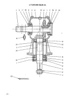
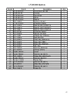
Page 22: ...20 LF 205 808 Gearbox ...

Page 23: ...asher 25x44x4 1 13 8 4 1 0093 Parallel Key 10x8x30 1 14 8 1 1 00054 Bolt M10x20 4 15 8 5 2 00030 Snap Ring 80x83x2 5 1 16 8 5 3 00955 Snap Ring SB81 1 17 8 5 2 00648 Snap Ring 62x65x3 1 18 8 6 6 00301 3 8 Plug 2 19 8 7 1 00748 Dust Lip 40x80x12 1 20 8 7 0 00744 Oil Cap 72x10 1 21 0 205 1300 00 Cover 1 22 0 244 7500 00 Shim Kit 40 3x51 5 1 23 8 5 1 00680 Snap Ring 40x37 5x2 5 1 24 0 248 7500 00 Shi...

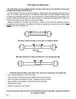
Page 24: ...ease to the outside of the small tube Reinstall the shields Install on equipment and recheck These procedures need to be done before first putting into operation and when attaching to a different tractor THIRD ANGLE PROJECTION 1 2 CL 1 3 CL 5 4 3 Folder DWG NO Model SCALE 1 DATE DRAWN MATERIAL P January 12 17 4 23 36 PM DESCRIPTION Weight lbs Width Height Length Blank Size Unit of Measure ITEM ID C...

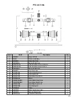
Page 25: ...ring Pin 8x50 mm 1 17 08002011 Inner Tube Yoke 1 25 021902C001 Cone Shield Bell 01 02 2 26 025502C001 Outer Bearing 02 1 27 025402C001 Outer Base Cone 01 02 1 28 0998052242 Screw 6 29 0988961NB2081 Outer Safety Shield Tube 1 30 0988955NB2081 Inner Safety Shield Tube 1 31 025402C002 Inner Base Cone 01 02 1 32 025502C002 Inner Bearing 02 1 40 025000001 Chain 1 48 09872006 Drive Tube Danger Label 1 4...

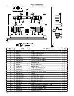
Page 26: ...1 21 091102S60 FREE WHEEL 1 25 021902C001 CONE SHIELD BELL 01 02 2 26 025502C001 OUTER BEARING 02 1 27 025402C001 OUTER BASE CONE 01 02 1 28 0998052242 SCREW 6 29 0988961NB2081 OUTER SAFETY TUBE 1 30 0988955NB2081 INNER SAFETY TUBE 1 31 025402C002 INNER BASE CONE 01 02 1 32 025502C002 INNER BEARING 02 1 40 0252000001 CHAIN 2 48 09872006 LABEL DANGER OUTER DRIVE TUBE 1 49 09872010 EXTERNAL SHIELD L...

Page 27: ...d paint to keep the metal from rusting Replace any caution warning danger or instruction safety decal that is not readable or is missing The servicing periods are based on normal operating conditions Severe or unusual conditions may require more frequent lubrication or oil changes 8 Hours or Daily 1 Lubricate PTO drive line 4 locations 2 Lubricate Castor Shafts 4 Locations 3 Check Belt Tension 20 ...

Page 28: ...43 49 67 70 95 1 2 49 66 76 105 105 145 5 8 97 130 150 205 210 285 3 4 144 195 265 360 375 510 7 8 165 225 430 585 605 820 1 250 340 645 875 910 1230 1 1 8 355 480 795 1080 1290 1750 1 1 4 500 680 1120 1520 1820 2460 1 1 2 870 1180 1950 2640 3160 4290 Allen head cap screw are similar to SAE 8 quality These torques are for reference only Not all these sizes and grades are necessarily used in this m...

Page 29: ......

Page 30: ...MK Martin Enterprise Inc 3950 Steffler Rd Elmira ON Canada N3B 2Z3 Tel 519 664 2752 Toll Free 1 855 664 2752 Fax 519 664 3695 E mail sales mkmartin ca www mkmartin ca ...

Reviews: