


MK-2005G
Revision 12/00, Effective Date December 26, 2000
Page 24
SETUP, STARTUP, ADJUSTMENT, OPERATION and SHUTDOWN
(K)
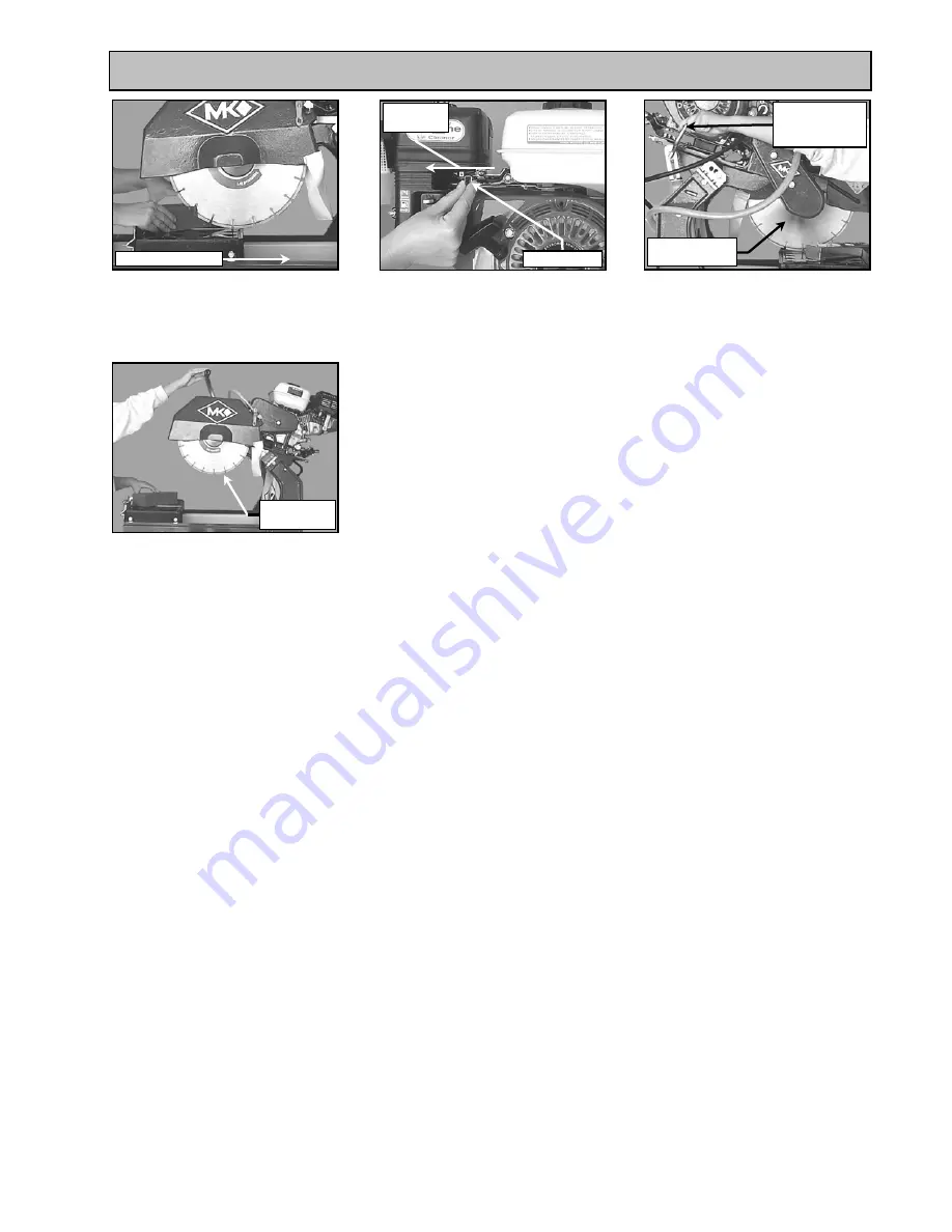
Move the Throttle Lever to
lower blade speed
(J)
Slowly push piece toward the
blade – continue until the
cut Is complete
(L)
Unlock Cutting Head
(M)
Raise Cutting Head once
cut is complete
Push Slowly to Cut
Direction of
Movement
Unlock Cutting
Head
Loosen Locking
Handle to adjust
Cutting Head
Throttle Lever
Raise Cutting
Head


