background image

8-12

Chapter 8 PERIODIC INSPECTION AND MAINTENANCE PROCEDURES

Fuel Pipe - Inspect

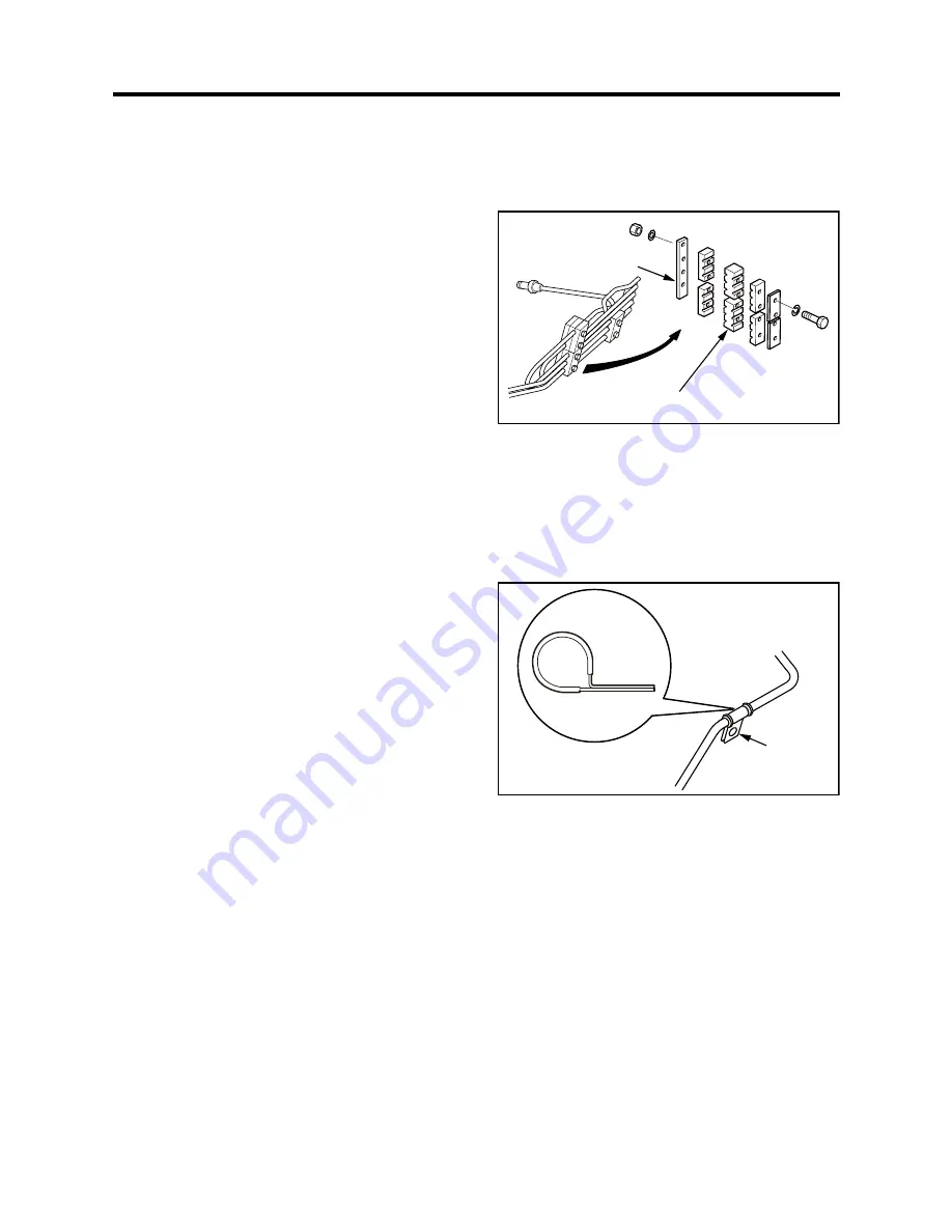
High Pressure Fuel Injection Pipe and Clamp Seat - Inspect and Replace

Visual Inspection

Check clamp seat for cracks and wear. Check high 
pressure fuel injection pipe for wear. If defective, 
replace the clamp seat with a new one. Replace the 
high pressure fuel injection pipe with a new one if 
needed.

During Every Major Overhaul

Replace clamp seat with a new one. Also, check high 
pressure fuel injection pipe for wear. If defective, 
replace the high pressure fuel injection pipe with a 
new one.

During Every Other Major Overhaul

Replace all high pressure fuel injection pipes with new 
ones.

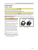
Fig. 8-13 High Pressure Fuel Injection Pipe and 

Clamp Seat - Inspect and Replace

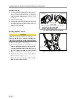
Low Pressure Fuel Pipe and Clip - Inspect

Visual Inspection During Overhaul 

Loosen clamp retaining bolts and check for clip wear 
and metal contact between pipe and clamp. If defec-
tive, replace the pipe assembly with a new one.

During Every Other Major Overhaul

Replace the pipe assembly with a new one.

Fig. 8-14 Low Pressure Fuel Pipe and Clip - Inspect

Clamp plate

Clamp seat

Clamp

Summary of Contents for S16R2-PTAW

Page 1: ... requested to read this Oper ation and Maintenance Manual carefully before operating the engine or conducting inspection and maintenance Never operate the engine or conduct maintenance work with out completely understanding this manual OPERATION MAINTENANCE MANUAL 1 ...

Page 2: ......

Page 3: ...ome contents are repeated among chapters for better understanding Please read and understand this manual before proceeding with operation inspection and maintenance work Failure to follow instructions in this manual may result in serious accidents Please observe the contents of the controls which are applied in the countries or areas when using the engines from Mitsubishi Heavy Industries Ltd ...

Page 4: ...rpose or use or against infringement of any patent Mitsubishi Heavy Industries Ltd will not be liable for any damages or consequential damages including but not limited to damages or other costs resulting from any abuse misuse misapplication of the engine and devices supplied from us Mitsubishi Heavy Industries Ltd will not be liable for any damages or personal injuries resulting from any modifica...

Page 5: ...tained and inspected only by qualified persons who have thor ough knowledge of engines and their dangers and who also have received risk avoidance training To prevent an accident do not attempt to carry out any operation other than those described in this man ual and do not use the engine for any unapproved purpose When the ownership of the engine is transferred be sure to give this manual to the ...

Page 6: ... directions could lead to serious accidents which could result in personal injury or death in the worst case Understand the directions well and handle engines by following directions Indicates an immediately hazardous situation which if not avoided will result in death or serious injury Indicates a potentially hazardous situation which if not avoided could result in death or serious injury Indicat...

Page 7: ...Force 1 N 0 10197 kgf Horsepower 1 kW 1 341 HP 1 3596 PS Rotation speed 1 min 1 1 rpm Kinetic viscosity 1 mm2 s 1 cSt Abbreviations Standards and Others API American Petroleum Institute ASTM American Society for Testing and Materials ISO International Organization for Standardization JIS Japanese Industrial Standards LLC Long Life Coolant MIL Military Specifications and Standards MSDS Material Saf...

Page 8: ......

Page 9: ...reful When Opening and Closing of Radiator Cap 1 5 Do Not Touch a High Pressure Fuel Jet 1 5 Be Careful When Handling Fuel Engine Oil and Coolant LLC 1 6 Use Only Specified Fuel Engine Oil and LLC 1 6 Handle LLC Carefully 1 6 Proper Disposal of Waste Oil LLC and Coolant 1 6 If Problem Occurs 1 6 Stop Operation Immediately If You Notice Any Unusual Symptoms 1 6 Do Not Add Coolant Immediately After ...

Page 10: ...5 Stopping 3 16 Emergency Stop 3 16 Inspection After Stopping 3 16 Chapter 4 FUEL Recommended Fuel 4 1 Handling Fuel 4 1 Fuel Specification 4 2 Chapter 5 ENGINE OIL Recommended Engine Oil 5 1 Engine Oil Grade 5 1 Engine Oil Specifications 5 2 Selection of Oil Viscosity 5 3 Handling Engine Oil 5 4 Service Limits of Engine Oil 5 4 Definition of Properties of Engine Oil 5 5 Kinetic Viscosity 5 5 Base...

Page 11: ... Alternator Inspect 8 26 Chapter 9 LONG TERM STORAGE Storing Engine in an Inoperable Condition for 3 Months up to 1 Year 9 1 Preparation for Storage 9 1 Maintenance During Storage 9 2 When Using Engine After Storage 9 2 Storing Engine in an Operable Condition 9 2 Operating Engine for Maintenance 9 2 Chapter 10 TRANSPORTATION Lifting Engine 10 1 Chapter 11 TROUBLESHOOTING General Precautions 11 1 C...

Page 12: ... Check Fuel Control Link 3 11 Fig 3 17 Oil Filler and Oil Level Gauge 3 12 Fig 3 18 Air Cleaner Check for Clogging 3 13 Fig 3 19 Thermo Label of Damper 3 13 Fig 3 20 Manual Stop Lever 3 16 Fig 5 1 Engine Oil Grade 5 1 Fig 5 2 Selection of Oil Viscosity 5 3 Fig 6 1 GLASSY LLC 6 1 Fig 6 2 Coolant Freezing Temperature GLASSY PG GLASSY 6 7 Fig 8 1 Belt Tension Alternator Side Adjust 8 2 Fig 8 2 Belt T...

Page 13: ...ngine Oil Properties 5 4 Table 6 1 Water quality standards 6 1 Table 6 2 LLC Quality Requirements 6 3 Table 6 3 Recommended LLC Concentration 6 7 Table 7 1 Periodic Maintenance Chart for Continuous Use Engine 7 3 Table 7 2 Periodic Maintenance Chart for Emergency Engine 7 5 Table 8 1 Ribbed Belt Tension Force 8 3 Table 8 2 Types of Thermo Labels 8 6 Table 8 3 Specific Gravity of Electrolyte 8 25 T...

Page 14: ......

Page 15: ...rting up the engine Unburned fuel may explode in the exhaust pipe Keep Engine Surrounding Area Tidy and Clean Do not leave combustible or explosive materials such as fuel engine oil and LLC near the engine Such substances can cause fire or explosion Remove dust dirt and other foreign materials accu mulated on the engine and surrounding parts Such materials can cause a fire or the engine to overhea...

Page 16: ...water bat tery electrolyte etc use a flameproof light An ordi nary lighting apparatus may ignite gas and cause it to explode Prevent Electrical Wires From Short Circuiting Avoid inspecting or servicing the electrical system with the ground cable connected to the battery Otherwise a fire could result from short circuiting Be sure to dis connect the battery cable from the negative termi nal before p...

Page 17: ...clothing or tool is caught in rotating parts it could result in serious injury or death Lockout and Tagout Be sure to lockout tagout before starting inspection and maintenance work Lockout and tagout are effective methods of cutting off machines and equipment from energy sources To accomplish the lockout tagout remove the starter switch key place the battery switch to the OFF posi tion and attach ...

Page 18: ...the common bed Hangers of engine cannot be used Keep the angle formed by slings that is attached to hangers within 60 degrees If the angle exceeds this limit excessive load could be imposed on the hangers and this could damage the hangers and result in a serious accident Attach wire ropes to the hangers after removing pipe covers and insulators near the hangers If the sling contacts the engine par...

Page 19: ...heat shields Do not remove these heat shields If any of these heat shields have been removed owing to unavoidable circumstances during the work be sure to restore them after the work is completed Be Careful When Opening and Closing of Radiator Cap Never open the radiator cap while the engine is run ning or immediately after stopping Stop the engine and open the cap after the coolant temperature lo...

Page 20: ...h the applicable laws and regulations If Problem Occurs Stop Operation Immediately If You Notice Any Unusual Symp toms Stop the operation immediately if you notice any unusual noise odor or vibration In case of emer gency press the emergency stop button to stop the generator set Contact your local dealer if the cause of problem cannot be located after stopping the genera tor Continuous operation n...

Page 21: ...rvicing electrical components or conducting electric welding set the battery switch to Open OFF position or remove the plug from the negative ter minal to cut off the electrical current Battery electrolyte contains dilute sulfuric acid Care less handling of the battery can lead to loss of sight and or skin burns Also do not swallow the battery electrolyte Wear protective goggles and rubber gloves ...

Page 22: ...e to improper balance between fuel injection volume and governor operation or overrunning which could result in a serious acci dent Perform All Specified Pre oper ation Inspections and Periodic Inspections Conduct pre operation inspections and periodic inspections as described in this manual Failure to conduct specified inspections may cause various engine problems and damage to parts which may re...

Page 23: ...nd serious accidents Conduct Proper Maintenance of Air Cleaner or Pre cleaner Pay attention to the Air Cleaner or Pre cleaner main tenance Never service the air cleaner while the engine is run ning The turbocharger may suck particles of foreign materials into the engine and could result in serious accidents Remove the air cleaner slowly to prevent foreign ma terials accumulated on the element from...

Page 24: ...is turned OFF when the engine is running it stops the operation of meters and also may deteriorate alternator diode and transistor Precautions for Transporting Engines When transporting the engine on a truck consider the engine weight width and height to ensure safety Abide by road traffic law road vehicles act vehicle restriction ordinance and other pertinent laws ...

Page 25: ...er and soap Do not use cleaning solvents gasoline or other chemicals to prevent the letters from getting blurred or the adhesion from being weakened Replace damaged or fractured labels with new ones If any engine part on which a warning label is attached is replaced with a new one attach a new identical warning label to the new part To obtain new warning labels contact your local dealer Fig 1 1 Wa...

Page 26: ......

Page 27: ...t View Rear View Fig 2 2 Engine Rear View Aircooler coolant outlet Thermostat Aircooler water pump Aircooler water pump coolant drain cock Oil pump Engine water pump Engine coolant outlet Damper Governor actuator Turbocharger Turbocharger Exhaust gas outlet Flywheel O I T A O R N T ...

Page 28: ...rive Bypass oil filter Oil filter Rear hanger Intake air inlet Manual stop lever Fuel feed pump Engine coolant drain cock Behind of coupling cover Fuel injection pump Front Rear hanger Fuel filter Front hanger Alternator Engine coolant inlet Breather Fuel injection pump Fuel feed pump Engine coolant drain cock Behind of coupling cover Stop solenoid Intake air inlet Rear Front Oil filler Oil level ...

Page 29: ...the STOP position cut off the fuel supply to the engine Fig 2 5 Manual Stop Lever Stop Solenoid The stop solenoid is used for normal shutdown of engine operation The stop solenoid moves the rack of fuel injection pump to cut the fuel so that the engine stops The RUN ON type stop solenoid is equipped in this engine The stop solenoid is energized while the engine is running To stop the engine it is ...

Page 30: ...on describes about devices which transmit signals to instruments for operation Read carefully and under stand functions of each device Revolution Detection Pickup Located on the timing gear case and detects engine speed at all times Fig 2 7 Revolution Detection Pickup ...

Page 31: ...emperature becomes high and reaches the specified temperature Fig 2 8 Thermo Switch Oil Filter Differential Pressure Alarm Switch The oil filter alarm switch generates an alarm to stop the engine when the difference in pressure across the filter reaches the specified lever due to filter clogging Fig 2 9 Oil Filter Differential Pressure Alarm Switch Air Cleaner Indicator If the element is clogged t...

Page 32: ...ch and a ratchet handle turn the shaft 4 After turning pull out the shaft insert the plate in the shaft groove and tighten the bolts Fig 2 13 Manual Turning Gear Position When Turning Shaft Before starting the engine make sure that the turning gear is pulled out in the original position Starting the engine with the turning gear pushed in not only damages the ring gear but also may result in person...

Page 33: ...loat switch is checked add fuel to FULL level Check that the following contents are performed before the engine is operated Failure to do so may cause various problems and will shorten the service life of the engine Prevent from spreading water especially seawater or rainwater and entering foreign materials to the air inlet opening Prevent from entering foreign materials to the rotating parts Prev...

Page 34: ...d Air 1 Loosen the air vent plug on the fuel injection pump by rotating about 1 5 turns 2 Move the priming pump up and down When the fuel flow from the air vent plug becomes free of bubbles turn the priming pump clockwise while pushing it to lock 3 Tighten the air vent plug on the fuel injection pump Fig 3 3 Fuel Injection Pump Bleed Air When fuel overflows from the air vent plug wipe thoroughly w...

Page 35: ...ed Consult a dealer of Mitsubishi Heavy Industries Ltd for replacement of the priming pump Fig 3 4 Priming Pump Tightening Method Fig 3 5 Priming Pump Head Packing Never fail to tighten the priming pump to the speci fied angle If the priming pump is not firmly tightened internal thread will be worn due to engine vibration resulting in sudden ejection of the cap to cause fuel flow out Or if the pri...

Page 36: ...ks Repair if there is oil leak 10 With the stop knob placed in pulled position rotate the engine with starter for approx 10 seconds to circulate oil to the whole engine Stop the rotation for 1 minute then repeat the rotation two or three times to circulate the engine oil to each engine parts Note Also perform the Preparation of Cooling System described below 11 Start the engine and run at a no loa...

Page 37: ...oolant leaks Repair leakage if found 4 When coolant reaches the specified level close the radiator cap securely 5 With the manual stop lever placed in the pulled po sition crank the engine for approx 10 seconds us ing the starter Stop cranking for 1 minute then repeat the cranking two or three times to bleed the cooling system Note Prepare for the lubricating system and refilling the coolant to th...

Page 38: ...12 1 b For absolute air bleeding loosen the air vent plug 3 Check the radiator and other parts for coolant leaks Repair leakage if found 4 When coolant reaches the full level close the cool ant filler securely 5 While pulling the manual stop lever crank the en gine for approx 10 seconds using the starter Stop the operation for 1 minute then repeat the opera tion two or three times to bleed the coo...

Page 39: ...ting battery always connect the plug to the positive terminal first Remove all battery cables then charge the battery in a well ventilated area Make sure the cable clamps are securely installed on the battery terminals A loose cable clamp can cause sparks that may result in an explosion Before servicing electrical components or conducting electric welding set the battery switch to Open OFF posi ti...

Page 40: ...an 1 22 charge the battery Fig 3 14 Specific Gravity of Battery Electrolyte Check Table 3 1 Specific Gravity of Electrolyte Specific gravity at 20 C 68 F Conditions Remedy From 1 26 to 1 28 Fully charged From 1 22 to 1 26 Partially charged Charge Less than 1 22 Discharged Charge Float Electrolyte surface Electrolyte Glass tube ...

Page 41: ...ipped with a reserve tank fill the reserve tank with coolant to the FULL level line as well Always switch the water heater ON automatic mode through a whole year If the switch is not ON automatic mode each cylinder varies considerably in combustion and abundant white exhaust gas generates at the starting up the engine Unburned fuel may explode in the exhaust pipe Emergency generator with water hea...

Page 42: ...gine oil drain valve Closed Fuel Tank Oil Level Check Make sure that the fuel tank is filled to the specified level If the fuel level is low add fuel to the FULL level Note If the specification of fuel tank differs from the contents of this operation manual follow the fuel tank manufac turer s operation manual If the engine abnormality is observed during operation stop the engine and correct the p...

Page 43: ... the drain cock Fig 3 15 Fuel Tank Drain Water Fuel Control Link Check Check fuel control link for smooth movement Push the manual stop lever to the fuel increase direc tion check the movement of the rack cancel spring Then loosen your grip on the lever little by little mak ing sure the manual stop lever returns to the no fuel injection position smoothly Also check all ball joints for looseness an...

Page 44: ...her area for oil leaks Fig 3 17 Oil Filler and Oil Level Gauge Coolant Level Check If the coolant level is low add coolant to the specified level Note Determine the quantities of LLC based on the coolant capacity and the LLC concentration chart For the coolant refer to COOLANT 6 1 For the coolant capacity refer to MAIN SPECIFICATIONS 12 1 Always add engine oil to the specified level If the oil lev...

Page 45: ...label is recommenced for damper tem perature control Check the thermo label before start ing engine as instructed below 1 Ensure the heat sensitive part of thermo label is black 2 Record the highest temperature of heat sensitive part Record the temperature periodically by which you can check the abnormality of temperature al teration Note For damper temperature limit and damper in spection refer t...

Page 46: ...r then inspect for fuel engine oil and coolant or exhaust gas leaks from joints during warm up operation Before starting the engine make sure no one is near the engine and that tools are not left on or near the engine In a loud voice notify people in the area when starting the engine Do not apply load to the engine when starting Continuous operation of the starter will drain the battery power or c...

Page 47: ...n in the engine room If air ventilation in the engine room is not suffi cient the room temperature rises and can affect engine output and performance For the first 50 hours of a new or overhauled engine operate the engine under a light load for break in operation Do not operate the new engine under heavy load or severe conditions during the break in period as it will shorten the service life of th...

Page 48: ...ealer Stopping the engine abruptly during high speed operation or while engine is hot will shorten the engine life Before stopping the engine run the engine with the idle speed at low Rpm for 5 or 6 minutes to cool the engine and check the engine for abnormalities Do not race the engine immediately before shutting it down If the engine stops abnormally do not restart the engine immediately When th...

Page 49: ...mixing with fuel in the tank and also gives time for dust and water to separate and settle at the bottom of the tank When refilling clean the areas around the caps of drum and tank thoroughly before removing the caps Also clean your hands and the hose before refueling When using a hand operated pump be careful not to pump water or sed iment accumulated at the bottom of the storage tank Be sure to ...

Page 50: ...index new type 45 or higher JISK2280 1996 ISO DIS 4264 Kinetic viscosity 2 0 mm2 s 0 0031 in2 s or more at 30 C 86 F 8 0 mm2 s 0 0124 in2 s or more at 30 C 86 F JIS K 2283 2000 ISO 3104 Sulfur content 0 2 weight or lower 1 0 weight or lower Shorten lub oil change intervals JIS K 2541 2000 The content should be as low as the die sel fuel ISO 4260 ISO 8754 Water content and sediment 0 1 volume or lo...

Page 51: ... BDF Biodiesel fuel FAME Fatty Acid Methyl Ester BDF quality shall meet JIS K 2390 ASTM D 6751 or EN14214 BDF blending of 5 by volume or less is approved JIS K 2390 2008 Standard for FAME ASTM D 6751 EN 14214 Engine applications For engines operated under a high load for a long period e c continuous use For engines operated under a low load for a short period of time e c stand by use Selection acc...

Page 52: ......

Page 53: ...clas sification CF or CH 4 When using the CF class engine oil it must be certi fied according to API service classification CF by 2009 and satisfied the following Table of Recommended Limit of Engine Oil Properties 5 2 When using the CH 4 class engine oil the sulfur con tent of fuel must be 0 2 weight or lower Fig 5 1 Engine Oil Grade Use the engine oil recommended in this manual only Never use oi...

Page 54: ...K 2265 ISO 3679 ISO 2719 ISO 2592 Base Number Hydrochloric acid method Sulfur contents of fuel 1 0 weight or lower mgKOH g 10 or higher up to 13 JIS K 2501 ISO 3771 ISO 6618 ISO 6619 ISO 7537 0 2 weight or lower 8 or higher up to 13 Perchloric acid method Sulfur contents of fuel 1 0 weight or lower mgKOH g 13 or higher up to 16 0 2 weight or lower 11 or higher up to 16 Acid number mgKOH g 1 5 to 2...

Page 55: ...ropriate oil viscosity according to the ambient temperature Excessively high oil viscosity causes power loss and an abnormal rise of oil temperature while excessively low oil viscosity accelerates wear due to inadequate lubrication and also causes a decrease in engine out put Fig 5 2 Selection of Oil Viscosity Bubbling test 2 I mL 10 0 JIS K 2518 ISO 6247 II 30 0 III 10 0 Panel caulking test 3 300...

Page 56: ...ny of the following properties exceeds the limit replace the engine oil with new oil Before filling the engine with engine oil stop the engine and make sure there are no open flames and other fire hazards near the engine Leaked or spilled oil on hot surfaces or electrical components can cause a fire Wipe off any spilled oil immediately and thoroughly After filling oil securely close the filler cap...

Page 57: ...wear of engine parts Base Number Base number shows the ability to neutralize acids such as organic acid due to engine oil oxidation or sulfurous or sulfuric acid due to the sulfur content of fuel Because base number indicates the amount of dispersant detergent in oil it can be used to estimate consumption of basic dispersant detergent The ability to disperse sludge declines as dispersant detergent...

Page 58: ...mperfect combustion products sludge or soot metal abrasive particles and dust Insoluble is an indication of degra dation contamination of oil Dispersant detergent which is an additive in engine oil absorbs sludge particles and disperses them as fine particles in oil Total insoluble density and remain ing dispersibility can be obtained by measuring insolu ble and coagulated insoluble chemical speci...

Page 59: ...powder in engine oil due to abrasion by which worn parts can be located Water LLC or salt that should not be in engine oil can be detected Engine oil deteriorating conditions by which appropriate engine oil renewal intervals operating conditions proper inspection and maintenance schedule can be planned The engine oil analysis service can diagnose the internal condition of the engine without disass...

Page 60: ......

Page 61: ...s Genuine LLC Mitsubishi Heavy Industries Ltd recommends the use of our genuine long life coolant GLASSY long life coolant Ethylene glycol type and Eco friendly prod uct PG GLASSY long life coolant propylene glycol type which are most appropriate coolant for Mitsubi shi diesel engines Be sure to use our Genuine LLC Fig 6 1 GLASSY LLC Table 6 1 Water quality standards Item Chemical symbol Unit Reco...

Page 62: ... that does not meet our requirements General Quality Requirements for LLC LLC must be a homogeneous liquid without sedi ment When the LLC is diluted to 30 to 60 density the LLC shall not cause any problems such as corrosion and precipitation deposits in the engine cooling system LLC shall be mixed well with other non amine type LLC that meets this requirement and shall not sepa rate elements inclu...

Page 63: ... Bubbling character ASTM D3306 01 30 vol 4 0 ml or less 331 3 vol 150 ml 0 032 gal or less disappearance of bubble within 5 seconds Hard water adaptability 1 0 or less 50 vol Metallic causticity 88 2 C 190 3 60 F 336 2 Hr 30 vol E G 50 vol P G Metal speci men Mass change Aluminum 0 30 mg cm2 Cast iron 0 15 mg cm2 Steel 0 15 mg cm2 Brass 0 15 mg cm2 Solder 0 30 mg cm2 Copper 0 15 mg cm2 Appearance ...

Page 64: ...Pb NH4 10 ppm or less Circulation metal lic causticity 88 3 C 190 5 40 F 1000 2 Hr 30 vol E G Metal speci men Mass change Aluminum 0 60 mg cm2 Cast iron 0 30 mg cm2 Steel 0 30 mg cm2 Brass 0 30 mg cm2 Solder 0 60 mg cm2 Copper 0 30 mg cm2 Appearance of the specimen after testing No visible signs of corrosion on the surface excluding the area contacted to the spacer However discoloration is accepta...

Page 65: ...to 10 Acrylonitrile butadiene rubber Tensile strength change 0 to 10 Elongation change 15 to 15 Volume change 0 to 40 Hardness change 10 to 0 Ethylene propylene diene monomer Tensile strength change 0 to 10 Elongation change 30 to 0 Volume change 0 to 10 Hardness change 10 to 0 Storage stability vol 30 vol room temperature 6 Hr 0 3 or less Table 6 2 LLC Quality Requirements Property Standard ...

Page 66: ...ld coolant or LLC be accidentally swallowed induce vomiting immediately and seek medical attention If LLC should enter eyes flush immediately with plenty of water and seek medical attention LLC is toxic Never dispose of coolant containing LLC drained from engine into regular sewage For disposal of used coolant consult LLC distributor Be sure to renew LLC coolant at the intervals specified in this ...

Page 67: ...perature will rise due to the decrease in specific heat 4 Coolant temperature will increase by approx 1 5 C 34 7 F for 60 concentration of GLASSY ethylene glycol and approx 3 C 37 4 F for 85 concentration of PG GLASSY propylene glycol Check heat exchanger capac ity of the cooling system to avoid overheating Fig 6 2 Coolant Freezing Temperature GLASSY PG GLASSY Table 6 3 Recommended LLC Concentrati...

Page 68: ...condition generates more severe corrosion than when plain soft water is used This is a typical problem caused by the use of inap propriate LLC Examples of Abnormali ties Caused by LLC Amine Type Pitting of Iron Parts Amines are generally effective in suppressing the rust ing of ferrous metals but they are said to become cor rosion promoter for copper parts Dissolved copper copper corrosion in the ...

Page 69: ...ollowing 3 categories Periodic Maintenance Chart for Regular Use Engine When the engine is used as a regular use engine perform the periodic inspection and maintenance in accordance with the Periodic Maintenance Chart for Engine in Regular Use Periodic Maintenance Chart for Emergency Engine When the engine is used as an emergency engine perform the periodic inspection and maintenance in accordance...

Page 70: ...er a fluctuating load throughout a day for supplying rated electric power in lieu of commercial power General Definition of Emergency Engine An engine used for emergency power generation such as main power supply and commercial power supply General Definition of General purpose Engine An engine used for a purpose other than power generation for example to drive a pump as the main engine for a ship...

Page 71: ...e hours for a new or overhauled engine Valve Clearance Inspect and Adjust Check valve mechanism at the same time 2 Every 1000 service hours Fuel Filter Replace 8 10 Water Separator Inspect and Replace 1 2 Belt and Belt Tension Inspect and Adjust 8 2 Gauze Filter Clean 8 9 Every 2000 hours Fuel Tank Drain Water Replace Parts As Needed 1 8 7 Valve Clearance Inspect and Adjust Check valve mechanism a...

Page 72: ...ridges valve springs tappets camshaft thrust plates pistons piston pins connecting rod bolts connecting rod bushings rocker bushings fuel pipe assembly oil pipe assembly 2 Fuel Injection Pump Inspect and Test Replace parts as needed 2 Governor Inspect and Test Replace parts as needed 2 Protective Devices Repair or Replace 1 High coolant temperature low oil pressure overspeeding starting failure wa...

Page 73: ...l vibration abnormal noise abnormal smell and gauge indication oil pressure gauge coolant temperature gauge oil temperature gauge exhaust temperature gauge tachometer etc Every month Fuel and Water Ingress In Engine Oil Inspect 8 16 Fuel Control Link Check 3 11 Battery Electrolyte Level Inspect 1 3 7 Conducting Engine Maintenance Operation Operate the engine with more than 1 2 load for 15 to 30 mi...

Page 74: ...emble and Clean 1 2 Strainer Including With Ball Tap of Cooling Water Inspect Disassemble and Clean 1 2 Coolant Properties When Only Soft Water is Used Inspect Change Coolant Based on Analysis Results 2 Air intake system Air Cleaner Element Clean Check and Replace 1 8 22 Pre cleaner Clean Inspect and Replace 1 8 21 Every year Electrical System Starter Inspect 8 26 Alternator Inspect 8 26 Specific ...

Page 75: ... Pump Discoloration and Other External Defects Check 2 Fuel Tank Clean 1 8 7 Fuel Injection Pump Inspect and Test Replace parts as needed 2 Governor Inspect and Test Replace parts as needed 2 Radiator Fins Check and Clean 1 2 Rubber Hose Replace 2 Protective Devices Repair or Replace 1 Oil pressure gauge coolant temperature gauge oil temperature gauge exhaust temperature gauge tachometer 2 Every 8...

Page 76: ...ur local dealer Every 8 years Vibration isolating Rubber Repair or Replace 1 2 Couplings Repair or Replace 1 2 Protective Devices Repair or Replace 1 2 Protective Devices Repair or Replace 1 2 Stop Solenoid Inspect or Replace 2 Ball Tap of Water Tank Repair or Replace 1 2 Other Consumable Parts Replace 2 Table 7 2 Periodic Maintenance Chart for Emergency Engine Inspection and maintenance intervals...

Page 77: ...s pulled out in it s original position 4 Make sure fluids such as fuel oil and coolant are not leaking from the engine If a leak is found repair the leak or contact your local dealer 5 Make sure the following valves plugs or cocks are properly positioned Fuel feed valve Open Coolant drain cock plug Closed Engine oil drain valve Closed Check external parts of the engine particularly hot part exhaus...

Page 78: ... 8 1 Belt Tension Alternator Side Adjust Belt Tension Air Cooler Water Pump Side Adjust 1 Loosen all the slide plate retaining bolts of tension pulley bracket 2 Loosen the lock nut of Air Cooler water pump ad justing bolt 3 Turn the adjusting bolt to adjust the belt tension 4 After adjusting deflection fix lock nuts of adjusting bolt 5 Tighten all slide plate retaining bolts of Air Cooler water pu...

Page 79: ... 17 77 lbf 59 N 6 02 kgf 13 27 lbf 47 N 4 79 kgf 10 56 lbf 39 N 3 98 kgf 8 77 lbf 7 132 N 13 46 kgf 29 67 lbf 88 N 8 97 kgf 19 78 lbf 66 N 6 73 kgf 14 84 lbf 53 N 5 40 kgf 11 90 lbf 44 N 4 49 kgf 9 90 lbf 8 147 N 14 99 kgf 33 05 lbf 98 N 9 99 kgf 22 02 lbf 74 N 7 55 kgf 16 64 lbf 59 N 6 02 kgf 13 27 lbf 49 N 5 00 kgf 11 02 lbf 9 162 N 16 52 kgf 36 42 lbf 108 N 11 01 kgf 24 27 lbf 81 N 8 26 kgf 18 ...

Page 80: ...62 N 6 32 kgf 13 93 lbf 46 N 4 69 kgf 10 34 lbf 37 N 3 77 kgf 8 31 lbf 31 N 3 16 kgf 6 97 lbf 8 103 N 10 50 kgf 23 15 lbf 69 N 7 04 kgf 15 52 lbf 51 N 5 20 kgf 11 46 lbf 41 N 4 18 kgf 9 22 lbf 34 N 3 47 kgf 7 65 lbf 9 113 N 11 52 kgf 25 40 lbf 75 N 7 65 kgf 16 87 lbf 57 N 5 81 kgf 12 81 lbf 45 N 4 59 kgf 10 12 lbf 38 N 3 87 kgf 8 54 lbf 10 123 N 12 54 kgf 27 65 lbf 82 N 8 36 kgf 18 43 lbf 62 N 6 3...

Page 81: ...ting Mit subishi Heavy Industries Ltd inspects each engine before shipment to make sure that the temperature of damper does not excessively rise However the damper temperature varies depending on ambient conditions Therefore make sure to provide sufficient ventilation for damper by following the instructions below 1 Make sure the temperature of the damper outer surface does not exceed 90 C 194 F w...

Page 82: ...at you can tell if there is any abnormal temperature change Note a When the increase in thermo label temperature is observed look for the abnormality of engine or other causes Then replace the thermo label with new one and check the temperature change again b If the temperature indication of thermo label comes close to the limit temperature of damper or if there is any abnormal temperature changes...

Page 83: ... water it can cause not only decrease of output but also malfunctions of the fuel system To avoid such a problem drain fuel tank as instructed below 1 Place a fuel container capacity of 2 L 0 5 US gal or more under the drain cock of fuel tank 2 Open the drain cock of fuel tank and drain fuel at least 1 to 2 L 0 3 to 0 5 US gal 3 After making sure water and foreign material parti cles has been disc...

Page 84: ...and drain fuel in the water separator 4 Close the all drain cocks after draining 5 Replace the element with a new one 6 Fill the water separator with fuel 7 Attach the water separator cover and tighten the T handle 8 Open the inlet cock and outlet cock 9 After replacing the element open the fuel feed valve to the engine then bleed air from the fuel system Note a For bleeding fuel system refer to F...

Page 85: ... feed pump 2 Using a screw driver remove the gauze filter that is fitted inside the union bolt 3 Soak the gauze filter in the fuel and clean it with a brush 4 After cleaning install the gauze filter into the union bolt using a screw driver 5 Install the union bolt to the fuel feed pump 6 Bleed air from the fuel filter Note For bleeding the fuel filter refer to Fuel Filter Bleed Air 3 2 Fig 8 8 Gau...

Page 86: ...the filter bracket further rotate 3 4 to a full turn 8 After the new fuel filter has been installed bleed the fuel filter Note For bleeding the fuel filter refer to Fuel Filter Bleed Air 3 2 9 Start the engine and run at idle speed for several minutes 10 Make sure that there is no fuel leak during engine operation If the leak is found loosen the fuel filter and check the gaskets for damage If ther...

Page 87: ... one If the ball joints are integrated with the control link replace the control link assembly When installing ball joints be sure to tighten the nuts firmly Fig 8 11 Ball Joints Looseness Inspect Fig 8 12 Fuel Control Link Remove If the sealed ball joints are found loosened contact your local dealer If the seal on the ball joint is bro ken the engine is no longer covered under warranty Ball joint...

Page 88: ...ssure fuel injection pipe for wear If defective replace the high pressure fuel injection pipe with a new one During Every Other Major Overhaul Replace all high pressure fuel injection pipes with new ones Fig 8 13 High Pressure Fuel Injection Pipe and Clamp Seat Inspect and Replace Low Pressure Fuel Pipe and Clip Inspect Visual Inspection During Overhaul Loosen clamp retaining bolts and check for c...

Page 89: ... oil or replacing oil filters be sure to wear gloves You can get burned if you touch the hot engine oil or parts Do not dump waste oil It is forbidden by law For disposal of waste oil consult a dealer of Mitsubishi Heavy Indus tries Ltd Engine oil oil filter and bypass oil filter should be changed at the same time Also engine oil analysis is recommended when changing engine oil Do not reuse oil fi...

Page 90: ... 6 Apply clean engine oil to gasket 7 Install oil filters and bypass oil filter to the filter bracket When the gasket comes in contact with the mounting surface of the filter bracket further ro tate 3 4 to a full turn Fig 8 15 Oil Filter and Bypass Oil Filter Replace Fig 8 16 Oil Filter If filter case is dented do not use the filter It can damage the filter during operation and may result in a fir...

Page 91: ...ngine oil 7 Install the oil filler cap after adding engine oil 8 Check the oil pan and other area for oil leaks Re pair if there is oil leak 9 With the manual stop lever placed in pulled posi tion rotate the engine with starter for approx 10 seconds to circulate oil to the whole engine Stop the rotation for 1 minute then repeat the rotation two or three times to circulate the engine oil to each en...

Page 92: ...sture vapor is discharged from the breather In such case locate the fuel or water leak and repair properly Note If oil leaks from oil cooler oil will float in water in the freshwater tank Also LLC that is not miscible with oil will accumulate at the bottom of oil pan Oil Pipe Inspect Oil Pipe and Clip Inspect and Replace Visual Inspection at Overhaul Loosen clamp fixing bolt and check clips and pi...

Page 93: ...ose engine For emergency use engine replace coolant once every 2 years Never open the radiator cap during the operation or immediately after the stop Stop the engine and open the cap after the coolant temperature lowers suffi ciently Place a waste cloth over the radiator cap and loosen the cap about a quarter turn or stand the lever to the upright position to release internal pressure The coolant ...

Page 94: ...non cor rosive to rubber and metals into the cooling sys tem and operate the engine at 800 to 900 min 1 for about 15 minutes then drain the cleaning solution 3 Close coolant drain cocks and plugs 4 Add fresh water and operate the engine at 800 to 900 min 1 for about 10 minutes Repeat the above rinsing steps until the draining water becomes clear and clean Fig 8 21 Coolant Drain Cock water pump Coo...

Page 95: ... coolant leaks Repair leakage if found 4 When coolant reaches the specified level close the radiator cap securely 5 With the manual stop lever placed in the pulled po sition crank the engine for approx 10 seconds us ing the starter Stop cranking for 1 minute then repeat the cranking two or three times to bleed the cooling system Note Prepare for the lubricating system and refilling the coolant to ...

Page 96: ...AIN SPECIFICATIONS 12 1 b For absolute air bleeding loosen the air vent plug 3 Check the radiator and other parts for coolant leaks Repair leakage if found 4 When coolant reaches the full level close the cool ant filler securely 5 While pulling the manual stop lever crank the en gine for approx 10 seconds using the starter Stop the operation for 1 minute then repeat the opera tion two or three tim...

Page 97: ...oreign materials from entering the engine and keeps the engine clean for optimum performance Always keep it clean as instructed below 1 Remove the pre cleaner from the silencer and hand wash the pre cleaner with a mild detergent 2 Rinse the pre cleaner with fresh water 3 After drying thoroughly inspect the pre cleaner for damage such as breaks If breaks or etc are found replace the pre cleaner wit...

Page 98: ...aterial to enter the engine and it results in rapid wear of parts leading to a shorter ser vice life of the engine Never tap or hit the air cleaner element And also do not wash the air cleaner element If defects such as a cut pinhole or local wear are found in the element or if the air cleaner indicator shows a red sign soon after the cleaned element is installed change it with a new one Remove th...

Page 99: ... inside surface again 5 After cleaning hold the air cleaner element near a light bulb to illuminate the inside to check for de fects such as cuts pinholes or local wear 6 If any defect is found replace the air cleaner ele ment with a new one 7 Reassemble the air cleaner element as it was 8 After cleaning or replacing the air cleaner element press the reset button to reset the indicator Note If the...

Page 100: ... When connecting battery always connect the plug to the positive terminal first Remove all battery cables then charge the battery in a well ventilated area Make sure the cable clamps are securely installed on the battery terminals A loose cable clamp can cause sparks that may result in an explosion Before servicing electrical components or conducting electric welding set the battery switch to Open...

Page 101: ... C 68 F is lower than 1 22 charge the battery Fig 8 33 Specific Gravity of Battery Electrolyte Check Table 8 3 Specific Gravity of Electrolyte Specific gravity at 20 C 68 F Conditions Remedy From 1 26 to 1 28 Fully charged From 1 22 to 1 26 Partially charged Charge Less than 1 22 Discharged Charge Float Electrolyte surface Electrolyte Glass tube ...

Page 102: ...ct Alternator Inspect Visually inspect the alternator for damage Remove the belt and turn the pulley by hand to check if it rotates smoothly Check the pulley for wear Also visually inspect the inside of alternator for dust and salt accumulation since the alternator is an air cooling type Note If the alternator is defective consult a dealer of Mitsubishi Heavy Industries Ltd Fig 8 35 Alternator Ins...

Page 103: ...1 Disconnect the cables from the battery terminals and charge the battery Clean the terminals apply a thin coat of grease to the terminals and store the battery in a cool and dry room 12 Cover the whole engine Note a Store the engine in a well ventilated and dried indoor area b It is not necessary to drain coolant since it contains LLC LLC must be the specified concentration For LLC concentration ...

Page 104: ...ter Stop the operation for approx 1 minute then repeat the operation two or three times 12 After starting make sure the engine oil pressure rises 13 Conduct a warm up operation for a sufficient duration to fully lubricate all the components Note For starting the engine refer to Starting up 3 14 14 Apply load and increase the engine speed to the rated speed Storing Engine in an Operable Condition I...

Page 105: ...ne is cou pled with a generator use the special hangers pro vided on the common bed Hangers of engine cannot be used Keep the angle formed by slings attached to hangers within 60 degrees If the angle exceeds this limit excessive load will be imposed on the hangers and this could damage the hangers and result in a seri ous accident Attach wire ropes to the hangers after removing pipe covers and ins...

Page 106: ......

Page 107: ... parts When disassembling a component take measures to prevent dust and foreign materials from entering the component being disassembled Cautions Regarding Parts Han dling Handle parts carefully When replacing parts use only genuine parts by refer ring to the parts catalogue Safety Work Be sure to use a tool suitable for the size Using a tool of wrong size can cause not only the damage to the part...

Page 108: ... Electrical system Faulty wire connection Check fuse Check wiring connection of each relay between battery starter and starter switch Insufficiently charged battery Check alternator Refer to P8 26 Check and adjust belt Refer to P8 2 Weak battery Check specific gravity of battery electrolyte Refer to P8 24 Charge the battery Change battery Faulty starter or starter relay Consult a dealer of Mitsubi...

Page 109: ... of Mitsubishi Heavy Industries Ltd Clogged fuel filter Inspect and replace fuel filter Refer to P8 10 Clean gauze filter Refer to P8 9 Faulty fuel feed pump operation Consult a dealer of Mitsubishi Heavy Industries Ltd Faulty fuel injection pump Check fuel injection pump rack stroke Consult a dealer of Mitsubishi Heavy Industries Ltd Faulty fuel injection nozzle Consult a dealer of Mitsubishi Hea...

Page 110: ...Check fuel injection pump rack stroke Check left and right bank Consult a dealer of Mitsubishi Heavy Industries Ltd Cooling system Overheat overcooled Check fan and radiator Check control system Consult a dealer of Mitsubishi Heavy Industries Ltd Inlet and exhaust systems Insufficient amount of air Check turbocharger Refer to P8 21 Clean Inspect and Replace Air Cleaner Element Refer to P8 22 Clean...

Page 111: ...subishi Heavy Industries Ltd Uneven fuel injection Check ignition noise exhaust smoke temperature left and right bank balance Consult a dealer of Mitsubishi Heavy Industries Ltd Incorrect fuel injection timing Consult a dealer of Mitsubishi Heavy Industries Ltd Lubricating system Combustion of engine oil Check amount of engine oil and lubrication system Refer to P3 12 Consult a dealer of Mitsubish...

Page 112: ... Industries Ltd Uneven fuel injection Check exhaust smoke temperature left and right bank bal ance Consult a dealer of Mitsubishi Heavy Industries Ltd Inlet and exhaust systems Insufficient amount of air Check turbocharger Refer to P8 21 Clean Inspect and Replace Air Cleaner Element Refer to P8 22 Check intake air pressure and leakage of intake air Check intake air temperature and ventilation devi...

Page 113: ...i Heavy Industries Ltd Cooling system Overcooled Check radiator Check control system Inspect thermostat Consult a dealer of Mitsubishi Heavy Industries Ltd Inlet and exhaust systems Insufficient amount of air Check turbocharger Refer to P8 21 Clean Inspect and Replace Air Cleaner Element Refer to P8 22 Check intake air pressure and leakage of intake air Check intake air temperature and ventilation...

Page 114: ...viscosity too low Use appropriate oil viscosity Refer to P5 3 Engine oil temperature is high Check amount of engine oil and lubrication system Refer to P3 12 Check oil cooler and oil thermostat Consult a dealer of Mitsubishi Heavy Industries Ltd Cooling system Overheating Check radiator Check control system Inspect thermostat Consult a dealer of Mitsubishi Heavy Industries Ltd Inlet and exhaust sy...

Page 115: ...l Check coolant leakage Check Coolant Level Refer to P3 13 Faulty water pump operation Consult a dealer of Mitsubishi Heavy Industries Ltd Faulty thermostat operation Consult a dealer of Mitsubishi Heavy Industries Ltd Faulty radiator operation Clean and inspect the radiator and radiator Control system Increase in load Check fuel injection pump rack stroke Check control system and governor control...

Page 116: ...gine oil property viscos ity Analyze oil property Use appropriate engine oil Refer to P5 7 Engine oil temperature is high Cooling System Check Consult a dealer of Mitsubishi Heavy Industries Ltd Clogged oil filter Inspect and replace oil filter and bypass oil filter Refer to P8 13 Faulty oil pump operation Consult a dealer of Mitsubishi Heavy Industries Ltd Faulty relief valve operation Consult a ...

Page 117: ...8 20 x 79 90 in Dry weight Approx 7750 kg 17086 lb Fuel Diesel fuel Fuel injection pump Mitsubishi PS8A 2 Fuel filter Paper element type Spin on type Fuel injection nozzle Hole type Fuel injection starting pressure 34 32 MPa 350 kgf cm2 4978 psi Lubrication method Forced circulation pressure feed by oil pump Engine Oil Grade CF or CH 4 oil API service classification Engine oil capacity Oil pan App...

Page 118: ......

Page 119: ...September 2012 Pub No 99400 71100 OPERATION MAINTENANCE MANUAL ...

Page 120: ...Printed in Japan Pub No 99400 71100 ...

Reviews: