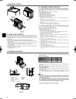
SW1
CNDM
7
8. Special Functions
8.1. Low noise mode (on-site modi
fi
cation) (Fig. 8-1)
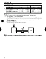
The low noise mode will be activated when a commercially available timer or the
contact input of an ON/OFF switch is added to the CNDM connector (option) on the
control board of the outdoor unit.
1
Complete the circuit as shown when using the external input adapter
(PAC-SC36NA). (Option)
2
SW1 ON: Low noise mode
SW1 OFF: Normal operation
Note:
•
The ability varies according to the outdoor temperature and conditions, etc.
•
When the ambient temperature is high, this function may not work.
A
Circuit diagram example
(low noise mode)
B
On-site arrangement
C
External input adapter
(PAC-SC36NA)
D
Outdoor unit control board
E
Max. 10 m
F
Red
G
Brown
H
Orange
Fig. 8-1
7. Test run
Before test run
►
After installation works are completed, check if there is no refrigerant leak-
age, no looseness in the power supply or control wiring, no wrong polarity,
and no disconnection of one phase in the supply.
►
Use a 500-volt megohmmeter to check that the resistance between the
power supply terminals and ground is at least 1.0M
"
.
Warning:
Do not use the air to water heat pump if the insulation resistance is less than
1.0M
"
.
Insulation resistance
When installed the power source to the unit has been cut for an extended period,
the insulation resistance may drop below 1 M
"
due to the accumulation of refriger-
ant within the compressor. This is not a malfunction. Perform the following proce-
dures.
1. Remove the wires from the compressor and measure the insulation resistance of
the compressor.
2. If the insulation resistance is below 1 M
"
, the compressor may be faulty or sim-
ply the accumulation of refrigerant in the compressor makes the resistance drop.
3. After connecting the wires to the compressor, the compressor starts to warm
up once power is supplied. After supplying power for the times indicated below,
remove the wires from the compressor and measure the insulation resistance
again.
• The insulation resistance drops due to the accumulation of refrigerant in the
compressor. The resistance will rise above 1 M
"
after the compressor is
warmed up for 4 hours.
(The necessary time to warm up the compressor varies according to atmo-
spheric conditions and refrigerant accumulation.)
• If the refrigerant accumulates within the compressor, the compressor must be
warmed up at least 12 hours before starting the operation to prevent break-
down.
4. If the insulation resistance rises above 1 M
"
, the compressor is not faulty.
Caution:
•
The compressor does not operate if the power supply phase connection is
incorrect.
•
Turn on the power at least 12 hours before starting operation.
-
Starting operation immediately after turning on the main power switch can result
in severe damage to internal parts. Keep the power switch turned on during the
operating period.
Note : Occasionally, vapor that is made by the defrost operation may seem as
if smoke come up from the outdoor unit.
01̲ BH79D067L02̲EN.indd 7
01̲ BH79D067L02̲EN.indd 7
2009/06/03 9:51:03
2009/06/03 9:51:03
Summary of Contents for PUHZ-HW*HA series
Page 8: ......

