


24
Your company internal use only.
Copyright (C) Mitsubishi Electric Corporation.
NR-242UM-13LND0,13-WS
DISASSEMBLING PROCEDURES
●
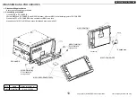
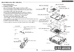
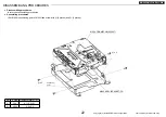
Disassembling procedures
In reverse of assembling procedures.
●
Assembling procedures
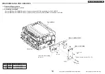
1.Attach M065 to M049 and screw with
Ⓒ
. (4 places)
2.Connect M005 to M065.
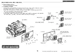
3.Attach S4-LCD to M049 and screw with
Ⓒ
. (4 places)
* When assemble it, use the jig for positioning.
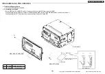
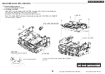
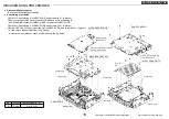
4.Attach M064 and M063 to M049 and screw with
Ⓒ
. (By 4 places)
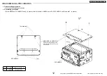
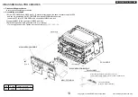
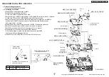
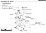
5.In the same way as a lower fig., connect M004 and M005 to
PCB and S4-LCD.
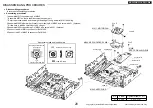
The upper part of the
terminal surface.
Lock a connector after
the insertion in FFC.
Lock a connector after
the insertion in FFC.
Lock a connector after
the insertion in FFC.
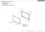
Take off a protection sheet of the touch
panel surface.
The blue reinforcement
board side.
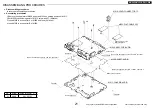
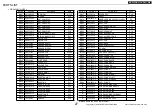
No.
Screw Tighten torque(N
・m)
Ⓒ
2X6
0.16
~
0.24
After having read QR code, take off LABEL-QR.
M049: ASSY-PAN
Positioning
Lock a connector after
the insertion in FFC.
Ⓒ
x 4
Ⓒ
x 4
Ⓒ
x 4
Ⓒ
x 4
M063: ASSY-PCB-SW-RIGHT
M004:FLAT-CABLE 16P
M064:
ASSY-PCB-SW-LEFT
M065:ASSY-PCB-SW-UNDER
M005:
FLAT-CABLE 10P
S4-LCD


